Sign In
Upload
Manuals
Brands
Mitsubishi Electric Manuals
Servo Drives
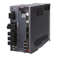
MR-J4W2-44B
Mitsubishi Electric MR-J4W2-44B Manuals
Manuals and User Guides for Mitsubishi Electric MR-J4W2-44B. We have
2
Mitsubishi Electric MR-J4W2-44B manuals available for free PDF download: Instruction Manual, Instructions And Cautions For Safe Use
Mitsubishi Electric MR-J4W2-44B Instruction Manual (588 pages)
General-Purpose AC Servo MELSERVO-J4 SSCNET /H Interface Multi-axis AC Servo MR-J4W series SERVO AMPLIFIER
Brand:
Mitsubishi Electric
| Category:
Servo Drives
| Size: 4.76 MB
Table of Contents
Table of Contents
10
Summary
18
Function Block Diagram
20
Servo Amplifier Standard Specifications
21
Integrated 3-Axis Servo Amplifier
23
Servo Amplifier
24
Combinations of Servo Amplifiers and Servo Motors
25
Function List
27
Model Designation
29
Parts Identification
30
Configuration Including Auxiliary Equipment
31
Installation Direction and Clearances
32
Keep out Foreign Materials
34
Inspection Items
36
Parts Having Service Life
37
Restrictions When Using this Product at Altitude Exceeding 1000 M and up to 2000 M above Sea Level
38
Signals and Wiring
41
Input Power Supply Circuit
41
I/O Signal Connection Example
44
For Source I/O Interface
46
Explanation of Power Supply System
47
Power-On Sequence
49
Wiring CNP1, CNP2, and CNP3
50
Connectors and Pin Assignment
52
Signal (Device) Explanations
53
Output Device
54
Output Signal
57
Forced Stop Deceleration Function
58
Base Circuit Shut-Off Delay Time Function
60
Vertical Axis Freefall Prevention Function
61
Alarm Occurrence Timing Chart
62
When You Do Not Use the Forced Stop Deceleration Function
64
Interfaces
65
Detailed Description of Interfaces
66
Source I/O Interfaces
67
SSCNET III Cable Connection
68
Servo Motor with an Electromagnetic Brake
70
Timing Chart
72
Grounding
77
Startup
78
Startup Procedure
79
Switching Power on for the First Time
79
Wiring Check
80
Surrounding Environment
81
Switch Setting and Display of the Servo Amplifier
83
Scrolling Display
88
Status Display of an Axis
89
Test Operation
91
Test Operation Mode in MR Configurator2
92
Motor-Less Operation in Controller
94
Parameter List
99
Basic Setting Parameters ([Pr. PA_ _ ])
100
Gain/Filter Setting Parameters ([Pr. PB_ _ ])
101
Extension Setting Parameters ([Pr. PC_ _ ])
102
I/O Setting Parameters ([Pr. PD_ _ ])
104
Extension Setting 2 Parameters ([Pr. PE_ _ ])
105
Extension Setting 3 Parameters ([Pr. PF_ _ ])
107
Linear Servo Motor/DD Motor Setting Parameters ([Pr. PL_ _ ])
108
Detailed List of Parameters
110
Gain/Filter Setting Parameters ([Pr. PB_ _ ])
120
Extension Setting Parameters ([Pr. PC_ _ ])
134
I/O Setting Parameters ([Pr. PD_ _ ])
141
Extension Setting 2 Parameters ([Pr. PE_ _ ])
145
Extension Setting 3 Parameters ([Pr. PF_ _ ])
147
Linear Servo Motor/DD Motor Setting Parameters ([Pr. PL_ _ ])
150
Different Adjustment Methods
154
Adjustment Using MR Configurator2
155
One-Touch Tuning
156
One-Touch Tuning Flowchart
158
Display Transition and Operation Procedure of One-Touch Tuning
160
Caution for One-Touch Tuning
170
Auto Tuning
171
Auto Tuning Mode Basis
172
Adjustment Procedure by Auto Tuning
173
Response Level Setting in Auto Tuning Mode
174
Manual Mode
175
Gain Adjustment Mode
178
Filter Setting
182
Machine Resonance Suppression Filter
183
Adaptive Filter II
186
Shaft Resonance Suppression Filter
188
Low-Pass Filter
189
Command Notch Filter
194
Gain Switching Function
196
Function Block Diagram
197
Parameter
198
Gain Switching Procedure
201
Tough Drive Function
205
Instantaneous Power Failure Tough Drive Function
207
Compliance with SEMI-F47 Standard
211
Model Adaptive Control Disabled
213
Explanation for the Lists
214
Alarm List
215
Warning List
225
Troubleshooting at Power on
228
Dimensions
230
Characteristics
236
Overload Protection Characteristics
236
Power Supply Capacity and Generated Loss
237
Dynamic Brake Characteristics
240
Dynamic Brake Operation
241
Permissible Load to Motor Inertia When the Dynamic Brake Is Used
243
Inrush Currents at Power-On of Main Circuit and Control Circuit
244
Cable Bending Life
244
Options and Peripheral Equipment
246
Cable/Connector Sets
246
Combinations of Cable/Connector Sets
247
SSCNET III Cable
249
Battery Cable/Junction Battery Cable
251
MR-D05UDL3M-B STO Cable
252
Selection of Regenerative Option
253
Parameter Setting
255
Connection of Regenerative Option
256
Dimensions
257
Battery
258
MR-BAT6V1SET-A Battery
259
MR-BT6VCASE Battery Case
262
MR-BAT6V1 Battery
268
MR Configurator2
269
System Configuration
270
Precautions for Using USB Communication Function
271
Selection Example of Wires
272
Molded-Case Circuit Breakers, Fuses, Magnetic Contactors
274
Power Factor Improving AC Reactors
276
Relays (Recommended)
277
Earth-Leakage Current Breaker
284
EMC Filter (Recommended)
287
Junction Terminal Block MR-TB26A
290
Summary
292
Confirmation of Absolute Position Detection Data
293
Battery
294
Using MR-BT6VCASE Battery Case
295
Introduction
296
Residual Risks of the STO Function
297
Specifications
298
Maintenance
299
Signal (Device) Explanations
300
Connection Example
301
External I/O Signal Connection Example Using an MR-J3-D05 Safety Logic Unit
302
External I/O Signal Connection Example Using an External Safety Relay Unit
304
External I/O Signal Connection Example Using a Motion Controller
305
Detailed Description of Interfaces
306
Source I/O Interface
307
Functions and Configuration
310
Servo System with Auxiliary Equipment
311
Signals and Wiring
312
Operation and Functions
314
Magnetic Pole Detection
317
Home Position Return
325
Test Operation Mode in MR Configurator2
329
Operation from Controller
332
Function
334
Absolute Position Detection System
336
Characteristics
337
Power Supply Capacity and Generated Loss
338
Dynamic Brake Characteristics
340
Permissible Load to Motor Mass Ratio When the Dynamic Brake Is Used
341
Functions and Configuration
342
Servo System with Auxiliary Equipment
344
Signals and Wiring
345
Operation and Functions
346
Startup Procedure
347
Magnetic Pole Detection
348
Operation from Controller
356
Function
357
Characteristics
359
Power Supply Capacity and Generated Loss
360
Dynamic Brake Characteristics
362
Functions and Configuration
366
Selecting Procedure of Control Mode
368
System Configuration
369
Load-Side Encoder
370
MR-J4FCCBL03M Branch Cable
371
Operation and Functions
372
Home Position Return
379
Operation from Controller
382
Fully Closed Loop Control Error Detection Functions
384
Auto Tuning Function
385
Absolute Position Detection System under Fully Closed Loop System
386
About MR Configurator2
387
J3 Compatibility Mode
390
J3 Compatibility Mode Supported Function List
391
How to Switch J4 Mode/J3 Compatibility Mode
394
How to Use the J3 Compatibility Mode
395
Cautions for Switching J4 Mode/J3 Compatibility Mode
396
Change of Specifications of "J3 Compatibility Mode" Switching Process
398
J3 Extension Function
400
Scale Measurement Function
454
Scale Measurement Encoder
456
How to Use Scale Measurement Function
459
Functions and Configuration
462
Circuit Protector
463
Function Block Diagram
463
Servo Amplifier Standard Specifications
464
Combinations of Servo Amplifiers and Servo Motors
465
Function List
466
Model Definition
468
Parts Identification
469
Configuration Including Peripheral Equipment
470
Installation
471
Installation Direction and Clearances
472
Installation by DIN Rail
474
Signals and Wiring
476
Input Power Supply Circuit
477
Explanation of Power Supply System
479
I/O Signal Connection Example
484
Connectors and Pin Assignment
487
Signal (Device) Explanations
488
Alarm Occurrence Timing Chart
495
Interfaces
497
Grounding
500
Startup
501
Startup Procedure
502
Surrounding Environment
504
Switch Setting and Display of the Servo Amplifier
505
Dimensions
506
Characteristics
507
Power Supply Capacity and Generated Loss
508
Inrush Currents at Power-On of Main Circuit and Control Circuit
510
Options and Peripheral Equipment
511
Cable/Connector Sets
512
Selection Example of Wires
514
Appendix
516
Service
560
Advertisement
Mitsubishi Electric MR-J4W2-44B Instructions And Cautions For Safe Use (2 pages)
MELSERVO-J4 Series; MR-J4 series Multi-axis Servo amplifier
Brand:
Mitsubishi Electric
| Category:
Amplifier
| Size: 0.33 MB
Advertisement
Related Products
Mitsubishi Electric MR-J4W3-444B
Mitsubishi Electric MR-J4W3-222B
Mitsubishi Electric MR-J4W2-77B
Mitsubishi Electric MR-J4W2-1010B
Mitsubishi Electric MR-J4W2-22B
Mitsubishi Electric MR-J4-22KA4(-RJ)
Mitsubishi Electric MR-J4-100B4(-RJ)
Mitsubishi Electric MELSERVO MR-J4-A-RJ Series
Mitsubishi Electric MELSERVO MR-J4-20B
Mitsubishi Electric MR-J4 B Series
Mitsubishi Electric Categories
Air Conditioner
Controller
Projector
Inverter
Heat Pump
More Mitsubishi Electric Manuals
Login
Sign In
OR
Sign in with Facebook
Sign in with Google
Upload manual
Upload from disk
Upload from URL