Sign In
Upload
Manuals
Brands
Mitsubishi Electric Manuals
Amplifier
MR-J5-A Series
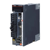
Mitsubishi Electric MR-J5-A Series Manuals
Manuals and User Guides for Mitsubishi Electric MR-J5-A Series. We have
4
Mitsubishi Electric MR-J5-A Series manuals available for free PDF download: User Manual, Introduction Manual
Mitsubishi Electric MR-J5-A Series User Manual (180 pages)
AC Servo System
Brand:
Mitsubishi Electric
| Category:
Controller
| Size: 10.86 MB
Table of Contents
Safety Instructions
3
About the Manual
5
U.s. Customary Units
5
Table of Contents
6
Chapter 1 Servo Parameter Details
13
Explanation of Servo Parameters
13
Basic Setting Servo Parameters Group ([Pr. PA
14
[Pr. Pa01_Operation Mode (**STY)]
14
[Pr. Pa02_Regenerative Option (**REG)]
15
[Pr. Pa03_Absolute Position Detection System (*ABS)]
16
[Pr. Pa04_Function Selection A-1 (*AOP1)]
16
[Pr. Pa05_Number of Command Input Pulses Per Revolution (*FBP)]
17
[Pr. Pa06_Electronic Gear - Numerator (CMX)]
17
[Pr. Pa07_Electronic Gear - Denominator (CDV)]
17
[Pr. Pa08_Auto Tuning Mode (ATU)]
18
[Pr. Pa09_Auto Tuning Response (RSP)]
20
[Pr. Pa10_In-Position Range (INP)]
21
[Pr. Pa11_Forward Rotation Torque Limit (TLP)]
21
[Pr. Pa12_Reverse Rotation Torque Limit (TLN)]
21
[Pr. Pa13_Command Pulse Input Form (*PLSS)]
22
[Pr. Pa14_Travel Direction Selection (*POL)]
24
[Pr. Pa15_Encoder Output Pulses (*ENR)]
25
[Pr. Pa16_Encoder Output Pulses 2 (*ENR2)]
25
[Pr. Pa17_Servo Motor Series Setting (**MSR)]
26
[Pr. Pa18_Servo Motor Type Setting (**MTY)]
27
[Pr. Pa19_Servo Parameter Writing Prohibited (*BLK)]
28
[Pr. Pa20_Tough Drive Setting (*TDS)]
29
[Pr. Pa21_Function Selection A-3 (*AOP3)]
30
[Pr. Pa22_Position Control Configuration Selection (**PCS)]
30
[Pr. Pa23_Drive Recorder Desired Alarm Trigger Setting (DRAT)]
31
[Pr. Pa24_Function Selection A-4 (AOP4)]
31
[Pr. Pa25_One-Touch Tuning - Overshoot Permissible Level (OTHOV)]
31
[Pr. Pa26_Function Selection A-5 (*AOP5)]
32
[Pr. Pa28_Function Selection A-6 (**AOP6)]
32
[Pr. Pa34_Quick Tuning - Permissible Travel Distance (QDIS)]
32
Gain/Filter Setting Servo Parameters Group ([Pr. PB
33
[Pr. Pb01_Adaptive Tuning Mode (Adaptive Filter II) (FILT)]
33
[Pr. Pb02_Vibration Suppression Control Tuning Mode (Advanced Vibration Suppression Control II) (VRFT)]
34
[Pr. Pb03_Position Command Speed Adjustment Time Constant (Position Smoothing) (PST)]
34
[Pr. Pb04_Feed Forward Gain (FFC)]
35
[Pr. Pb06_Load to Motor Inertia Ratio/Load to Motor Mass Ratio (GD2)]
35
[Pr. Pb07_Model Control Gain
35
[Pr. Pb08_Position Control Gain
36
[Pr. Pb09_Speed Control Gain (VG2)]
36
[Pr. Pb10_Speed Integral Compensation (VIC)]
36
[Pr. Pb11_Speed Differential Compensation (VDC)]
36
[Pr. Pb12_Overshoot Amount Compensation (OVA)]
36
[Pr. Pb13_Machine Resonance Suppression Filter 1 (NH1)]
37
[Pr. Pb14_Notch Shape Selection 1 (NHQ1)]
37
[Pr. Pb15_Machine Resonance Suppression Filter 2 (NH2)]
37
[Pr. Pb16_Notch Shape Selection 2 (NHQ2)]
38
[Pr. Pb17_Shaft Resonance Suppression Filter (NHF)]
39
[Pr. Pb18_Low-Pass Filter Setting (LPF)]
43
[Pr. Pb19_Vibration Suppression Control 1 - Vibration Frequency (VRF11)]
43
[Pr. Pb20_Vibration Suppression Control 1 - Resonance Frequency (VRF12)]
43
[Pr. Pb21_Vibration Suppression Control 1 - Vibration Frequency Damping (VRF13)]
43
[Pr. Pb22_Vibration Suppression Control 1 - Resonance Frequency Damping (VRF14)]
44
[Pr. Pb23_Low-Pass Filter Selection (VFBF)]
44
[Pr. Pb24_Slight Vibration Suppression Control (*MVS)]
45
[Pr. Pb25_Function Selection B-1 (*BOP1)]
45
[Pr. Pb26_Gain Switching Function (*CDP)]
46
[Pr. Pb27_Gain Switching Condition (CDL)]
47
[Pr. Pb28_Gain Switching Time Constant (CDT)]
47
[Pr. Pb29_Load to Motor Inertia Ratio/Load to Motor Mass Ratio after Gain Switching (GD2B)]
47
[Pr. Pb30_Position Control Gain after Gain Switching (PG2B)]
47
[Pr. Pb31_Speed Control Gain after Gain Switching (VG2B)]
47
[Pr. Pb32_Speed Integral Compensation after Gain Switching (VICB)]
47
[Pr. Pb33_Vibration Suppression Control 1 - Vibration Frequency after Gain Switching (VRF11B)]
48
[Pr. Pb34_Vibration Suppression Control 1 - Resonance Frequency after Gain Switching (VRF12B)]
48
[Pr. Pb35_Vibration Suppression Control 1 - Vibration Frequency Damping after Gain Switching (VRF13B)]
48
[Pr. Pb36_Vibration Suppression Control 1 - Resonance Frequency Damping after Gain Switching (VRF14B)]
48
[Pr. Pb45_Command Notch Filter (CNHF)]
49
[Pr. Pb46_Machine Resonance Suppression Filter 3 (NH3)]
52
[Pr. Pb47_Notch Shape Selection 3 (NHQ3)]
52
[Pr. Pb48_Machine Resonance Suppression Filter 4 (NH4)]
52
[Pr. Pb49_Notch Shape Selection 4 (NHQ4)]
53
[Pr. Pb50_Machine Resonance Suppression Filter 5 (NH5)]
53
[Pr. Pb51_Notch Shape Selection 5 (NHQ5)]
54
[Pr. Pb52_Vibration Suppression Control 2 - Vibration Frequency (VRF21)]
54
[Pr. Pb53_Vibration Suppression Control 2 - Resonance Frequency (VRF22)]
55
[Pr. Pb54_Vibration Suppression Control 2 - Vibration Frequency Damping (VRF23)]
55
[Pr. Pb55_Vibration Suppression Control 2 - Resonance Frequency Damping (VRF24)]
55
[Pr. Pb56_Vibration Suppression Control 2 - Vibration Frequency after Gain Switching (VRF21B)]
55
[Pr. Pb57_Vibration Suppression Control 2 - Resonance Frequency after Gain Switching (VRF22B)]
56
[Pr. Pb58_Vibration Suppression Control 2 - Vibration Frequency Damping after Gain Switching (VRF23B)]
56
[Pr. Pb59_Vibration Suppression Control 2 - Resonance Frequency Damping after Gain Switching (VRF24B)]
56
[Pr. Pb60_Model Control Gain after Gain Switching (PG1B)]
56
[Pr. Pb65_Gain Switching 2 Condition (CDL2)]
57
[Pr. Pb66_Gain Switching 2 Time Constant (CDT2)]
57
[Pr. Pb67_Gain Switching 2 - Load to Motor Inertia Ratio/Load to Motor Mass Ratio (GD2C)]
57
[Pr. Pb68_Gain Switching 2 - Position Control Gain (PG2C)]
57
[Pr. Pb69_Gain Switching 2 - Speed Control Gain (VG2C)]
57
[Pr. Pb70_Gain Switching 2 - Speed Integral Compensation (VICC)]
57
[Pr. Pb71_Vibration Suppression Control 1 - Vibration Frequency after Gain Switching 2 (VRF11C)]
58
[Pr. Pb72_Vibration Suppression Control 1 - Resonance Frequency after Gain Switching 2 (VRF12C)]
58
[Pr. Pb73_Vibration Suppression Control 1 - Vibration Frequency Damping after Gain Switching 2 (VRF13C)]
58
[Pr. Pb74_Vibration Suppression Control 1 - Resonance Frequency Damping after Gain Switching 2 (VRF14C)]
59
[Pr. Pb75_Vibration Suppression Control 2 - Vibration Frequency after Gain Switching 2 (VRF21C)]
59
[Pr. Pb76_Vibration Suppression Control 2 - Resonance Frequency after Gain Switching 2 (VRF22C)]
59
[Pr. Pb77_Vibration Suppression Control 2 - Vibration Frequency Damping after Gain Switching 2 (VRF23C)]
60
[Pr. Pb78_Vibration Suppression Control 2 - Resonance Frequency Damping after Gain Switching 2 (VRF24C)]
60
[Pr. Pb79_Gain Switching 2 - Model Control Gain (PG1C)]
60
[Pr. Pb81_Command Filter (*CFIL)]
61
[Pr. Pb82_Position Command Smoothing Filtering Time Constant (PFT)]
61
Extension Setting Servo Parameters Group ([Pr. PC
62
[Pr. Pc01_Speed Acceleration Time Constant (STA)]
62
[Pr. Pc02_Speed Deceleration Time Constant (STB)]
62
[Pr. PC03_S-Pattern Acceleration/Deceleration Time Constants (STC)]
63
[Pr. Pc04_Torque Command Time Constant (TQC)]
63
[Pr. Pc05_Internal Speed 1 (SC1)]
64
[Pr. Pc06_Internal Speed 2 (SC2)]
64
[Pr. Pc07_Internal Speed 3 (SC3)]
64
[Pr. Pc08_Internal Speed 4 (SC4)]
64
[Pr. Pc09_Internal Speed 5 (SC5)]
64
[Pr. Pc10_Internal Speed 6 (SC6)]
64
[Pr. Pc11_Internal Speed 7 (SC7)]
65
[Pr. Pc12_Analog Speed Command - Maximum Speed (VCM)]
65
[Pr. Pc13_Analog Torque Command Maximum Output (TLC)]
65
[Pr. Pc14_Analog Monitor 1 Output (MOD1)]
66
[Pr. Pc15_Analog Monitor 2 Output (MOD2)]
67
[Pr. Pc16_Electromagnetic Brake Sequence Output (MBR)]
67
[Pr. Pc17_Zero Speed (ZSP)]
67
[Pr. Pc18_Alarm History Clear (*BPS)]
67
[Pr. Pc19_Encoder Output Pulses Selection (*ENRS)]
68
[Pr. Pc22_Function Selection C-1 (**COP1)]
71
[Pr. Pc23_Function Selection C-2 (*COP2)]
72
[Pr. Pc24_Function Selection C-3 (*COP3)]
73
[Pr. Pc26_Function Selection C-5 (*COP5)]
74
[Pr. Pc27_Function Selection C-6 (*COP6)]
75
[Pr. Pc28_Function Selection C-7 (*COP7)]
75
[Pr. Pc29_Function Selection C-8 (*COP8)]
76
[Pr. Pc30_Speed Acceleration Time Constant 2 (STA2)]
76
[Pr. Pc31_Speed Deceleration Time Constant 2 (STB2)]
77
[Pr. Pc32_Command Input Pulse Multiplication Numerator 2 (CMX2)]
77
[Pr. Pc33_Command Input Pulse Multiplication Numerator 3 (CMX3)]
77
[Pr. Pc34_Command Input Pulse Multiplication Numerator 4 (CMX4)]
77
[Pr. Pc35_Internal Torque Limit 2 (TL2)]
77
[Pr. Pc36_Status Display Selection (*DMD)]
78
[Pr. Pc37_Analog Command Input 1 Offset (VCO)]
80
[Pr. Pc38_Analog Command Input 2 Offset (TPO)]
80
[Pr. Pc39_Analog Monitor 1 Offset (MO1)]
81
[Pr. Pc40_Analog Monitor 2 Offset (MO2)]
81
[Pr. Pc43_Excessive Error Alarm Trigger Level (ERZ)]
81
[Pr. Pc44_Function Selection C-9 (**COP9)]
81
[Pr. Pc45_Function Selection C-A (**COPA)]
82
[Pr. Pc50_Function Selection C-B (*COPB)]
83
[Pr. Pc51_Deceleration Time Constant at Forced Stop (RSBR)]
84
[Pr. Pc54_Vertical Axis Freefall Prevention Compensation Amount (RSUP1)]
84
[Pr. Pc60_Function Selection C-D (**COPD)]
85
[Pr. Pc73_Excessive Error Warning Trigger Level (ERW)]
86
[Pr. Pc90_Command Frequency Error Threshold (PLFT)]
86
I/O Setting Servo Parameters Group ([Pr. PD
87
[Pr. Pd01_Input Signal Automatic on Selection 1 (*DIA1)]
87
[Pr. Pd03_Input Device Selection 1L (*DI1L)]
89
[Pr. Pd04_Input Device Selection 1H (*DI1H)]
90
[Pr. Pd05_Input Device Selection 2L (*DI2L)]
90
[Pr. Pd06_Input Device Selection 2H (*DI2H)]
90
[Pr. Pd07_Input Device Selection 3L (*DI3L)]
91
[Pr. Pd08_Input Device Selection 3H (*DI3H)]
91
[Pr. Pd09_Input Device Selection 4L (*DI4L)]
92
[Pr. Pd10_Input Device Selection 4H (*DI4H)]
92
[Pr. Pd11_Input Device Selection 5L (*DI5L)]
93
[Pr. Pd12_Input Device Selection 5H (*DI5H)]
93
[Pr. Pd13_Input Device Selection 6L (*DI6L)]
93
[Pr. Pd14_Input Device Selection 6H (*DI6H)]
94
[Pr. Pd17_Input Device Selection 8L (*DI8L)]
94
[Pr. Pd18_Input Device Selection 8H (*DI8H)]
94
[Pr. Pd19_Input Device Selection 9L (*DI9L)]
95
[Pr. Pd20_Input Device Selection 9H (*DI9H)]
95
[Pr. Pd21_Input Device Selection 10L (*DI10L)]
95
[Pr. Pd22_Input Device Selection 10H (*DI10H)]
96
[Pr. Pd23_Output Device Selection 1 (*DO1)]
96
[Pr. Pd24_Output Device Selection 2 (*DO2)]
97
[Pr. Pd25_Output Device Selection 3 (*DO3)]
97
[Pr. Pd26_Output Device Selection 4 (*DO4)]
97
[Pr. Pd28_Output Device Selection 6 (*DO6)]
98
[Pr. Pd29_Input Filter Setting (*DIF)]
98
[Pr. Pd30_Function Selection D-1 (*DOP1)]
99
[Pr. Pd31_Function Selection D-2 (*DOP2)]
100
[Pr. Pd32_Function Selection D-3 (*DOP3)]
100
[Pr. Pd33_Function Selection D-4 (*DOP4)]
100
[Pr. Pd34_Function Selection D-5 (*DOP5)]
101
[Pr. Pd43_Input Device Selection 11L (*DI11L)]
101
[Pr. Pd44_Input Device Selection 11H (*DI11H)]
102
[Pr. Pd45_Input Device Selection 12L (*DI12L)]
102
[Pr. Pd46_Input Device Selection 12H (*DI12H)]
102
[Pr. Pd47_Output Device Selection 7 (*DO7)]
103
[Pr. PD60_DI Pin Polarity Selection (*DIP)]
103
Extension Setting 2 Servo Parameters Group ([Pr. PE
105
[Pr. Pe01_Fully Closed Loop Control Function Selection 1 (**FCT1)]
105
[Pr. Pe03_Fully Closed Loop Control Function Selection 2 (*FCT2)]
106
[Pr. Pe04_Fully Closed Loop Control - Feedback Pulse Electronic Gear 1 - Numerator (**FBN)]
107
[Pr. Pe05_Fully Closed Loop Control - Feedback Pulse Electronic Gear 1 - Denominator (**FBD)]
107
[Pr. Pe06_Fully Closed Loop Control - Speed Deviation Error Detection Level (BC1)]
107
[Pr. Pe07_Fully Closed Loop Control - Position Deviation Error Detection Level (BC2)]
107
[Pr. Pe08_Fully Closed Loop Dual Feedback Filter (DUF)]
107
[Pr. Pe10_Fully Closed Loop Function Selection 3 (FCT3)]
108
[Pr. Pe41_Function Selection E-3 (EOP3)]
108
[Pr. Pe44_Lost Motion Compensation Positive-Side Compensation Value Selection (LMCP)]
108
[Pr. Pe45_Lost Motion Compensation Negative-Side Compensation Value Selection (LMCN)]
109
[Pr. Pe46_Lost Motion Filter Setting (LMFLT)]
109
[Pr. Pe47_Unbalanced Torque Offset (TOF)]
109
[Pr. Pe48_Lost Motion Compensation Function Selection (*LMOP)]
109
[Pr. Pe49_Lost Motion Compensation Timing (LMCD)]
109
[Pr. Pe50_Lost Motion Compensation Non-Sensitive Band (LMCT)]
110
[Pr. Pe51_Load-Side Encoder Resolution Setting (**EDV2)]
110
Extension Setting 3 Servo Parameters Group ([Pr. PF
111
[Pr. Pf02_Function Selection F-2 (*FOP2)]
111
[Pr. Pf09_Function Selection F-5 (*FOP5)]
112
[Pr. Pf15_Electronic Dynamic Brake Operating Time (DBT)]
113
[Pr. PF18_STO Diagnosis Error Detection Time (**STOD)]
113
[Pr. Pf21_Drive Recorder Switching Time Setting (DRT)]
113
[Pr. Pf23_Vibration Tough Drive - Oscillation Detection Level (OSCL1)]
114
[Pr. Pf24_Function Selection F-9 (*FOP9)]
114
[Pr. PF25_SEMI-F47 Function - Instantaneous Power Failure Detection Time (Instantaneous Power Failure Tough Drive Detection Time) (CVAT)]
114
[Pr. Pf31_Machine Diagnosis Function - Friction Judgment Speed (FRIC)]
115
[Pr. Pf32_Oscillation Detection Alarm Time (*VIBT)]
115
[Pr. Pf49_Friction Failure Prediction - Compensation Coefficient 1 (TSL)]
115
[Pr. Pf50_Friction Failure Prediction - Compensation Coefficient 2 (TIC)]
116
[Pr. Pf51_Machine Diagnosis Function Selection (*MFP)]
116
[Pr. Pf52_Machine Failure Prediction Servo Parameter (MFPP)]
118
[Pr. Pf53_Failure Prediction - Servo Motor Total Travel Distance (FPMT)]
119
[Pr. Pf54_Friction Failure Prediction - Average Characteristics (PAV)]
119
[Pr. Pf55_Friction Failure Prediction - Standard Deviation (PSD)]
119
[Pr. Pf56_Vibration Failure Prediction - Average Characteristics (VAV)]
120
[Pr. Pf57_Vibration Failure Prediction - Standard Deviation (VSD)]
120
[Pr. Pf58_Servo Motor Total Travel Distance Offset (TMO)]
120
[Pr. Pf66_Gear Setting for Backlash Estimation (BLG)]
120
[Pr. Pf67_Backlash Nominal Value (BLN)]
121
[Pr. Pf68_Backlash Threshold Multiplication (BLTT)]
121
[Pr. Pf69_Static Friction Failure Prediction - Average Characteristics (SPAV2)]
121
[Pr. Pf70_Static Friction Failure Prediction - Standard Deviation (SPSD2)]
121
[Pr. Pf71_Belt Failure Prediction Function Selection (BFP)]
122
[Pr. Pf72_Belt Tension on Installation (SBT)]
122
[Pr. Pf73_Belt Tension When Extended (ABT)]
122
[Pr. Pf74_Static Friction During Installation (SSF)]
122
[Pr. Pf75_Static Friction When Extended (ASF)]
123
[Pr. Pf76_Belt Tension Irregular Threshold (BTS)]
123
[Pr. Pf80_Drive Recorder - Operation Condition Selection (DRMC)]
124
[Pr. Pf81_Drive Recorder - Sampling Operation Selection (DRMS)]
125
[Pr. Pf82_Drive Recorder - Trigger Operation Selection (DRTM)]
125
[Pr. Pf84_Drive Recorder - Trigger Channel Selection (DRTC)]
127
[Pr. Pf85_Drive Recorder - Trigger Level Setting 1 (DRTL1)]
128
[Pr. Pf86_Drive Recorder - Trigger Level Setting 2 (DRTL2)]
128
[Pr. Pf87_Drive Recorder - Analog Channel Setting 1 (DRAC1)]
129
[Pr. Pf88_Drive Recorder - Analog Channel Setting 2 (DRAC2)]
131
[Pr. Pf89_Drive Recorder - Analog Channel Setting 3 (DRAC3)]
131
[Pr. Pf90_Drive Recorder - Analog Channel Setting 4 (DRAC4)]
132
[Pr. Pf91_Drive Recorder - Digital Channel Setting 1 (DRDC1)]
132
[Pr. Pf92_Drive Recorder - Digital Channel Setting 2 (DRDC2)]
134
[Pr. Pf93_Drive Recorder - Digital Channel Setting 3 (DRDC3)]
134
[Pr. Pf94_Drive Recorder - Digital Channel Setting 4 (DRDC4)]
135
[Pr. Pf95_Drive Recorder - Clear History (*DRCLR)]
135
Motor Extension Setting Servo Parameters Group ([Pr. PL
136
[Pr. Pl01_Function Selection L-1 (**LIT1)]
136
[Pr. Pl02_Linear Encoder Resolution Setting - Numerator (**LIM)]
136
[Pr. Pl03_Linear Encoder Resolution Setting - Denominator (**LID)]
136
[Pr. Pl04_Function Selection L-2 (*LIT2)]
137
[Pr. Pl05_Position Deviation Error Detection Level (LB1)]
137
[Pr. Pl06_Speed Deviation Error Detection Level (LB2)]
137
[Pr. Pl07_Torque Deviation Error Detection Level (LB3)]
138
[Pr. Pl08_Function Selection L-3 (*LIT3)]
138
[Pr. Pl09_Magnetic Pole Detection - Voltage Level (LPWM)]
138
[Pr. Pl17_Magnetic Pole Detection - Minute Position Detection Method - Function Selection (LTSTS)]
139
Chapter 2 Lists of Servo Parameter Supported Modes
142
Structure
142
Lists of Supported Control Modes
143
Basic Setting Servo Parameters Group ([Pr. PA
143
Gain/Filter Setting Servo Parameters Group ([Pr. PB
144
Extension Setting Servo Parameters Group ([Pr. PC
146
I/O Setting Servo Parameters Group ([Pr. PD
147
Extension Setting 2 Servo Parameters Group ([Pr. PE
148
Extension Setting 3 Servo Parameters Group ([Pr. PF
149
Motor Extension Setting Servo Parameters Group ([Pr. PL
151
Chapter 3 Lists of Servo Parameter Initial Values
152
Basic Setting Servo Parameters Group ([Pr. PA
152
Gain/Filter Setting Servo Parameters Group ([Pr. PB
153
Extension Setting Servo Parameters Group ([Pr. PC
155
I/O Setting Servo Parameters Group ([Pr. PD
157
Extension Setting 2 Servo Parameters Group ([Pr. PE
159
Extension Setting 3 Servo Parameters Group ([Pr. PF
161
Motor Extension Setting Servo Parameters Group ([Pr. PL
163
Chapter 4 Servo Parameter Setting Method
165
Engineering Tool
165
Operation Section (Push Buttons)
165
Chapter 5 Network Parameter Details
167
Network Basic Parameters
168
[Pr. NPA02_IP Address]
168
[Pr. Npa04_Subnet Mask]
168
[Pr. Npa08_Host Name]
168
User Authentication Parameters
169
[Pr. Npb01_User Authentication and Authorization Setting]
169
[Pr. Npb04_User Name No.1]
169
[Pr. Npb05_Authorization Level No.1]
169
[Pr. Npb06_Password No.1]
170
[Pr. Npb07_User Name No.2]
170
[Pr. Npb08_Authorization Level No.2]
170
[Pr. Npb09_Password No.2]
170
[Pr. Npb10_User Name No.3]
170
[Pr. Npb11_Authorization Level No.3]
170
[Pr. Npb12_Password No.3]
170
[Pr. Npb13_User Name No.4]
171
[Pr. Npb14_Authorization Level No.4]
171
[Pr. Npb15_Password No.4]
171
[Pr. Npb16_User Name No.5]
171
[Pr. Npb17_Authorization Level No.5]
171
[Pr. Npb18_Password No.5]
171
[Pr. Npb19_User Name No.6]
171
[Pr. Npb20_Authorization Level No.6]
172
[Pr. Npb21_Password No.6]
172
[Pr. Npb22_User Name No.7]
172
[Pr. Npb23_Authorization Level No.7]
172
[Pr. Npb24_Password No.7]
172
[Pr. Npb25_User Name No.8]
172
[Pr. Npb26_Authorization Level No.8]
172
[Pr. Npb27_Password No.8]
173
Chapter 6 Network Parameter Setting Method
174
Engineering Tool
174
Revisions
176
Warranty
177
Trademarks
178
Advertisement
Mitsubishi Electric MR-J5-A Series User Manual (216 pages)
AC Servo System
Brand:
Mitsubishi Electric
| Category:
Controller
| Size: 20.6 MB
Table of Contents
About the Manual
3
U.s. Customary Units
4
Table of Contents
5
Chapter 1 Servo Amplifier Troubleshooting
9
Outline
9
List of Alarm No./Warning no
11
Explanation of the List
11
Handling Methods for Alarms/Warnings
26
[AL. 010_Undervoltage]
26
[AL. 011_Switch Setting Error]
27
[AL. 012_Memory Error 1 (RAM)]
28
[AL. 013_CPU Error]
29
[AL. 014_Control Process Error]
30
[AL. 016_Encoder Initial Communication Error 1]
31
[AL. 017_Board Error]
33
[AL. 019_Memory Error 3]
35
[AL. 01A_Servo Motor Combination Error]
36
[AL. 01E_Encoder Initial Communication Error 2]
38
[AL. 01F_Encoder Initial Communication Error 3]
39
[AL. 020_Encoder Normal Communication Error 1]
40
[AL. 021_Encoder Normal Communication Error 2]
42
[AL. 024_Main Circuit Error]
43
[AL. 025_Absolute Position Erased]
44
[AL. 027_Initial Magnetic Pole Detection Error]
47
[AL. 028_Linear Encoder Error 2]
49
[AL. 02A_Linear Encoder Error 1]
50
[AL. 02B_Encoder Counter Error]
51
[AL. 030_Regenerative Error]
52
[AL. 031_Overspeed]
53
[AL. 032_Overcurrent]
54
[AL. 033_Overvoltage]
56
[AL. 035_Command Frequency Error]
57
[AL. 037_Parameter Error]
58
[AL. 03A_Inrush Current Suppression Circuit Error]
59
[AL. 042_Servo Control Error]
60
[AL. 045_Main Circuit Device Overheat]
63
[AL. 046_Servo Motor Overheat]
64
[AL. 047_Cooling Fan Error]
66
[AL. 050_Overload 1]
67
[AL. 051_Overload 2]
69
[AL. 052_Excessive Error]
70
[AL. 054_Oscillation Detection]
72
[AL. 056_Forced Stop Error]
73
[AL. 063_STO Timing Error]
74
[AL. 066_Encoder Initial Communication Error (Safety Sub-Function)]
75
[AL. 067_Encoder Normal Communication Error 1 (Safety Sub-Function)]
76
[AL. 068_STO Diagnosis Error]
77
[AL. 069_Command Error]
78
[AL. 070_Load-Side Encoder Initial Communication Error 1]
80
[AL. 071_Load-Side Encoder Normal Communication Error 1]
83
[AL. 072_Load-Side Encoder Normal Communication Error 2]
85
[AL. 076_Load-Side Encoder Error]
86
[AL. 086_Network Communication Error]
87
[AL. 088_Watchdog 1]/[AL. 888_Watchdog 1]/[AL. 88888_Watchdog 1]
88
[AL. 08A_Serial Communication Time-Out Error]
89
[AL. 08E_Serial Communication Error]
90
[AL. 090_Homing Incomplete Warning]
91
[AL. 091_Servo Amplifier Overheat Warning]
92
[AL. 092_Battery Cable Disconnection Warning]
93
[AL. 093_ABS Data Transfer Warning]
94
[AL. 095_STO Warning]
95
[AL. 096_Home Position Setting Warning]
96
[AL. 098_Software Position Limit Warning]
97
[AL. 099_Stroke Limit Warning]
98
[AL. 09B_Excessive Error Warning]
100
[AL. 09E_Network Warning]
101
[AL. 09F_Battery Warning]
103
[AL. 0E0_Excessive Regeneration Warning]
104
[AL. 0E1_Overload Warning 1]
105
[AL. 0E2_Servo Motor Overheat Warning]
107
[AL. 0E3_Absolute Position Counter Warning]
108
[AL. 0E5_ABS Time-Out Warning]
109
[AL. 0E6_Servo Forced Stop Warning]
110
[AL. 0E8_Cooling Fan Speed Reduction Warning]
111
[AL. 0E9_Main Circuit off Warning]
112
[AL. 0EA_ABS Servo-On Warning]
113
[AL. 0Eb_The Other Axis Error Warning]
114
[AL. 0Ec_Overload Warning 2]
115
[AL. 0Ed_Output Watt Excess Warning]
116
[AL. 0F0_Tough Drive Warning]
117
[AL. 0F2_Drive Recorder Warning]
118
[AL. 0F3_Oscillation Detection Warning]
119
[AL. 0F4_Positioning Warning]
120
[AL. 0F7_Machine Diagnosis Warning]
121
[AL. 118_Encoder Diagnosis]
123
[AL. 119_Memory Error 4]
124
[AL. 11A_Servo Motor Constant Error]
125
[AL. 130_Regenerative Error 2]
126
[AL. 139_Open-Phase Error]
127
[AL. 168_STO Function Error]
128
[AL. 17A_Load-Side Linear Encoder Error 1]
129
[AL. 188_Watchdog 2]
130
[AL. 19E_Network Warning 2]
131
[AL. 1E9_Open Phase Warning]
132
[AL. 1F8_Memory Warning 1]
133
[AL. 510_Voltage Diagnosis Error (Safety Sub-Function)]
134
[AL. 512_Memory Error 1 (RAM) (Safety Sub-Function)]
135
[AL. 514_Control Process Error (Safety Sub-Function)]
136
[AL. 515_Memory Error 2 (ROM) (Safety Sub-Function)]
137
[AL. 516_Encoder Initial Communication Error 1 (Safety Sub-Function)]
138
[AL. 517_Board Error (Safety Sub-Function)]
139
[AL. 518_Synchronous Control Error (Safety Sub-Function)]
140
[AL. 519_Memory Error 3 (Flash-ROM) (Safety Sub-Function)]
141
[AL. 520_Encoder Normal Communication Diagnosis Error 1 (Safety Sub-Function)]
143
[AL. 521_Encoder Normal Communication Diagnosis Error 2 (Safety Sub-Function)]
143
[AL. 522_Encoder Normal Communication Diagnosis Error 3 (Safety Sub-Function)]
144
[AL. 523_Encoder Normal Communication Diagnosis Error 4 (Safety Sub-Function)]
145
[AL. 524_Encoder Normal Communication Diagnosis Error 5 (Safety Sub-Function)]
146
[AL. 525_Encoder Normal Communication Diagnosis Error 6 (Safety Sub-Function)]
147
[AL. 526_Encoder Normal Communication Diagnosis Error 7 (Safety Sub-Function)]
148
[AL. 527_Encoder Normal Communication Diagnosis Error 8 (Safety Sub-Function)]
149
[AL. 528_Encoder Normal Communication Diagnosis Error 9 (Safety Sub-Function)]
150
[AL. 529_Encoder Data Error (Safety Sub-Function)]
151
[AL. 52A_Position Feedback Error (Safety Sub-Function)]
152
[AL. 52B_Encoder Thermal Error (Safety Sub-Function)]
153
[AL. 52C_ Encoder Normal Communication Error 10 (Safety Sub-Function)]
154
[AL. 537_Parameter Setting Range Error (Safety Sub-Function)]
155
[AL. 53A_Parameter Verification Error (Safety Sub-Function)]
156
[AL. 540_Internal Diagnosis Error 1 (Safety Sub-Function)]
157
[AL. 541_Internal Diagnosis Error 2 (Safety Sub-Function)]
158
[AL. 542_Internal Diagnosis Error 3 (Safety Sub-Function)]
159
[AL. 543_Internal Diagnosis Error 4 (Safety Sub-Function)]
160
[AL. 544_Temperature Diagnosis Error (Safety Sub-Function)]
161
[AL. 545_Internal Diagnosis Error 5 (Safety Sub-Function)]
162
[AL. 546_Internal Diagnosis Error 6 (Safety Sub-Function)]
163
[AL. 547_Internal Diagnosis Error 7 (Safety Sub-Function)]
164
[AL. 549_Internal Diagnosis Error 8 (Safety Sub-Function)]
165
[AL. 54A_Internal Diagnosis Error 9 (Safety Sub-Function)]
166
[AL. 54D_Internal Diagnosis Error 10 (Safety Sub-Function)]
167
[AL. 54F_Safety Software Error (Safety Sub-Function)]
168
[AL. 550_Internal Diagnosis Error 11 (Safety Sub-Function)]
169
[AL. 551_Internal Diagnosis Error 12 (Safety Sub-Function)]
170
[AL. 552_Internal Diagnosis Error 13 (Safety Sub-Function)]
171
[AL. 554_Input Device Internal Diagnosis Error (Safety Sub-Function)]
172
[AL. 555_Output Device Diagnosis Error 1 (Safety Sub-Function)]
173
[AL. 556_Output Device Diagnosis Error 2 (Safety Sub-Function)]
174
[AL. 557_Input Device Mismatch Detection (Safety Sub-Function)]
175
[AL. 560_Stop Error (Safety Sub-Function)]
176
[AL. 561_Safety Speed Monitor Error 1 (Safety Sub-Function)]
178
[AL. 562_Safety Speed Monitor Error 2 (Safety Sub-Function)]
180
[AL. 563_Deceleration Monitor Error (Safety Sub-Function)]
182
[AL. 564_Increment Monitor Error (Safety Sub-Function)]
184
[AL. 565_Direction Monitor Error (Safety Sub-Function)]
185
[AL. 568_Torque Monitor Error 1 (Safety Sub-Function)]
187
[AL. 569_Torque Monitor Error 2 (Safety Sub-Function)]
189
[AL. 580_Safety Communication Setting Error (Safety Sub-Function)]
191
[AL. 581_Safety Communication Error 1 (Safety Sub-Function)]
192
[AL. 582_Safety Communication Error 2 (Safety Sub-Function)]
194
[AL. 583_Safety Communication Error 3 (Safety Sub-Function)]
195
[AL. 595_STO Command off Warning (Safety Sub-Function)]
196
[AL. 596_SS1 Time-Out Warning (Safety Sub-Function)]
197
[AL. 59D_Internal Diagnosis Error (Safety Sub-Function)]
198
[AL. 5E1_Test Mode Setting Mismatch Warning (Safety Sub-Function)]
199
[AL. 5E2_Safety Communication Warning (Safety Sub-Function)]
200
[AL. 5E6_SS1 Command off Warning (Safety Sub-Function)]
201
Trouble Which Does Not Trigger an Alarm/Warning
202
The Display Shows "A" (Unconnected to the Controller)
202
The Display Shows "R
202
The Display Shows "TST
202
The Display Shows "Off
203
The Display Is off
203
The Servo Motor Does Not Operate
203
The Increase in the Servo Motor Speed Is Insufficient or Excessive
205
Vibration of Servo Motor at Low Frequency
205
There Is an Unusual Noise in the Servo Motor
206
The Servo Motor Vibrates
206
Poor Speed Accuracy (Unstable Speed of Servo Motor)
207
The Machine Vibrates Unsteadily When It Stops
207
Overshoot/Undershoot Occurs
207
The Servo Motor Starts Moving Immediately after the Power-On of the Servo Amplifier or Servo-On
208
The Home Position Deviates at the Homing
208
The Position Deviates During Operation after the Homing
209
A Position Mismatch Occurs at Power Restoration in an Absolute Position Detection System
210
Communication with the Servo Amplifier Fails Using MR Configurator2
210
Electromagnetic Brake Went out
210
Electromagnetic Brake Cannot be Released
210
Coasting Distance of the Servo Motor Became Longer
211
Communication (Mitsubishi Electric AC Servo Protocol) Cannot be Used
211
Revisions
212
Warranty
213
Trademarks
214
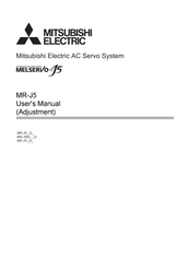
Mitsubishi Electric MR-J5-A Series User Manual (108 pages)
AC Servo System
Brand:
Mitsubishi Electric
| Category:
Amplifier
| Size: 10.15 MB
Table of Contents
Safety Instructions
3
About the Manual
5
Customary Units
5
Table of Contents
6
Chapter 1 Adjustment Function Types
9
Adjustment Function Available to Servo Amplifier Alone
9
Functions to Automatically Adjust Machine Stability
9
Adjustment Functions to Suppress Vibration and to Obtain a High Level of Responsiveness
10
Manual Adjustment Functions to Obtain the Maximum Performance
10
Adjustment Functions Available in Combination with MR Configurator2
11
Chapter 2 Adjustment Procedure
12
Chapter 3 Adjustment Method
14
Quick Tuning
14
Restrictions on Quick Tuning
14
Precautions on Quick Tuning
14
Setting Method for Quick Tuning
15
Operation of Quick Tuning
17
Errors in Quick Tuning
17
One-Touch Tuning
18
Restrictions on One-Touch Tuning
18
Instructions on One-Touch Tuning
19
One-Touch Tuning Procedure
19
Progress Display During One-Touch Tuning
30
Servo Parameters Adjusted with One-Touch Tuning
31
One-Touch Tuning Stop Method
32
One-Touch Tuning Error
33
Initializing One-Touch Tuning
36
Auto Tuning Mode 1
39
Restrictions on Auto Tuning Mode 1
39
Instructions on Auto Tuning Mode 1
39
Adjustment Procedure by Auto Tuning Mode 1
40
Responsiveness Setting in Auto Tuning Mode 1
41
Operation of Auto Tuning Mode 1
43
Auto Tuning Mode 2
43
Precautions on Auto Tuning Mode 2
43
Adjustment Procedure by Auto Tuning Mode 2
43
Responsiveness Setting in Auto Tuning Mode 2
44
Operation of Auto Tuning Mode 2
44
Gain Adjustment Mode 1
45
Adjustment Procedure of 2 Gain Adjustment Mode 1
45
Operation of 2 Gain Adjustment Mode 1
46
Gain Adjustment Mode 2
46
Adjustment Procedure of 2 Gain Adjustment Mode 2
46
Operation of 2 Gain Adjustment Mode 2
46
Manual Mode
47
Adjustment Procedure of Velocity Mode
47
Adjustment Procedure of Position Mode
49
Load to Motor Inertia Ratio Monitor Mode
51
Precautions on Load to Motor Inertia Ratio Monitor Mode
51
Adjustment Procedure of Load to Motor Inertia Ratio Monitor Mode
51
Operation of Load to Motor Inertia Ratio Monitor Mode
51
Chapter 4 Vibration Suppression Function
52
Filter Setting
52
Machine Resonance Suppression Filter
52
Machine Resonance Suppression Filter Restrictions
53
Machine Resonance Suppression Filter Precautions
53
Machine Resonance Suppression Filter Setting Method
53
Operation of Machine Resonance Suppression Filter
54
Adaptive Filter II
55
Restrictions on Adaptive Tuning
55
Precautions for Adaptive Filter II
55
How to Set Adaptive Filter II
56
Adaptive Tuning Procedure
56
Shaft Resonance Suppression Filter
57
Shaft Resonance Suppression Filter Restrictions
57
Shaft Resonance Suppression Filter Setting Method
57
Low-Pass Filter
61
Low-Pass Filter Setting Method
61
Operation of Low-Pass Filter
61
Robust Filter
61
Robust Filter Restrictions
61
Robust Filter Setting Method
61
Advanced Vibration Suppression Control II
62
Advanced Vibration Suppression Control Restrictions
63
Advanced Vibration Suppression Control Precautions
64
Advanced Vibration Suppression Control Setting Method
64
Advanced Vibration Suppression Control Adjustment Method
64
Command Notch Filter
68
Command Notch Filter Setting Method
69
Vibration Tough Drive
72
Vibration Tough Drive Restrictions
72
Vibration Tough Drive Precautions
72
Vibration Tough Drive Setting Method
72
Operation of Vibration Tough Drive
73
Chapter 5 Gain Switching Function
75
Restrictions on Gain Switching [G] [WG]
75
Restrictions on Gain Switching [A]
75
Precautions on Gain Switching [G] [WG]
75
Precautions on Gain Switching [A]
76
Setting Method for Gain Switching
76
Servo Parameters for Setting the Gain Switching Condition
76
Servo Parameters that Are Changeable with the Gain Switching
78
Related Objects [G] [WG]
79
Examples of Gain Switching Operation
80
Gain Switching by Servo Motor Speed
80
Gain Switching by Signals (CDP/C_CDP/CDP2/C_CDP2)
84
Gain Switching by Command Directions
86
Gain Switching by Servo Motor Speed and Gain Switching 2 (C_CDP2) [G] [WG]
88
Selected
89
Chapter 6 Speed Feed Forward Control Function
90
Method for Setting the Speed Feed Forward
90
Chapter 7 Overshoot Suppression Control
92
Restrictions on the Overshoot Suppression Control
92
Settings of the Overshoot Suppression Control
92
Chapter 8 Slight Vibration Suppression Control
94
Restrictions on the Slight Vibration Suppression Control
94
Settings of the Slight Vibration Suppression Control
94
Operation of Slight Vibration Suppression Control
94
Chapter 9 Unbalanced Torque Offset
96
Setting Unbalanced Torque Offset
96
Automatic Setting
96
Manual Setting
96
Chapter 10 Model Adaptive Control
98
Setting Model Adaptive Control
98
Disabling Model Adaptive Control
98
Instructions on Disabling Model Adaptive Control
98
How to Disable Model Adaptive Control
99
Chapter 11 Path Control Function
100
Path Tracking Model Adaptive Control
100
Setting the Path Tracking Model Adaptive Control
100
Operation of Path Tracking Model Adaptive Control
101
Lost Motion Compensation Function
101
Restrictions on Lost Motion Compensation Function
101
Setting the Lost Motion Compensation Function
101
Method for the Lost Motion Compensation Adjustment
102
Revisions
104
Warranty
105
Trademarks
106
Advertisement
Mitsubishi Electric MR-J5-A Series Introduction Manual (112 pages)
CC-Link IE TSN Drive Safety Device AC Servo System
Brand:
Mitsubishi Electric
| Category:
Industrial Electrical
| Size: 5.67 MB
Table of Contents
Introduction
3
Product Applications
3
Relevant Manuals
3
Table of Contents
4
Servo Amplifier Characteristics
6
Safety Communication Characteristics
9
System Configuration
10
About the Tools Used
11
Setting Flow
13
1.1 Devices to Prepare
14
CHAPTER 1 Preparation
15
Registering a Profile
16
1.3 Wiring
18
CHAPTER 2 Creating a Project
21
Creating a New Project
21
Programmable Controller Initialization
23
Registering User Information
25
Module Configuration
26
Parameter Settings
30
Network Configuration Settings
30
Servo Amplifier
34
Parameter Settings (Safety Remote I/O Module)
37
Safety Communication Settings
41
Safety Function Setting
41
Safety Communication Settings
42
Extended Parameter Settings
49
Servo Amplifier
50
Safety Remote I/O Module
55
Writing Extended Parameters
59
Safety Function Cancel Program
61
Program Writing
62
Safety Parameter Settings Using MR Configurator2
66
Setting the Servo Amplifier Safety Parameters
66
Writing the Safety Parameter Settings
71
Enabling the Safety Settings (Safety Remote I/O Module)
73
CHAPTER 3 Operation Check
81
Communication with the Safety Remote I/O Module
81
Checking that Safety Communication Settings Were Completed Correctly
81
Safety Monitoring Operation Check
82
CHAPTER 4 Troubleshooting
90
Segment LED Displays and Contents
90
Errors and Corrective Actions
92
CHAPTER 5 Switching Safety Operation Mode
93
Safety Operation Mode
93
How to Switch Safety Operation Mode
93
Checking after Switching Safety Operation Mode
94
Appendix
95
Appendix 1 Library Registration
95
Appendix 2 Sample Program
97
Revisions
109
Trademarks
110
Advertisement
Related Products
Mitsubishi Electric MR-J5W-G Series
Mitsubishi Electric MR-J5-G Series
Mitsubishi Electric Melservo MR-J5 G Series
Mitsubishi Electric Melservo MR-J5W G Series
Mitsubishi Electric MELSERVO MR-J5W2 G-N1 Series
Mitsubishi Electric MELSERVO MR-J5W3 G-N1 Series
Mitsubishi Electric MR-J2S-700CL
Mitsubishi Electric Melservo MR-J3-11KB4
Mitsubishi Electric MELSERVO MR-J2 C Series
Mitsubishi Electric MELSERVO MR-J2-20A
Mitsubishi Electric Categories
Air Conditioner
Controller
Projector
Inverter
Heat Pump
More Mitsubishi Electric Manuals
Login
Sign In
OR
Sign in with Facebook
Sign in with Google
Upload manual
Upload from disk
Upload from URL