Sign In
Upload
Manuals
Brands
Panasonic Manuals
Label Maker
LP-MA05-S-CHN
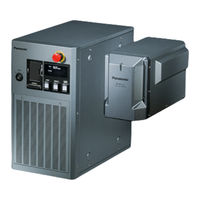
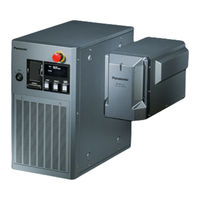
Panasonic LP-MA05-S-CHN Manuals
Manuals and User Guides for Panasonic LP-MA05-S-CHN. We have
3
Panasonic LP-MA05-S-CHN manuals available for free PDF download: Operation Manual, Serial Communication Manual, Maintenance Manual
Panasonic LP-MA05-S-CHN Serial Communication Manual (205 pages)
Laser Marker
Brand:
Panasonic
| Category:
Label Maker
| Size: 4.28 MB
Table of Contents
General Terms and Conditions of this Document
2
Cautions in Handling
2
Target Laser Marker
4
Symbol Indications
4
How to Read this Document
4
Type of Manuals
5
Safety / Setup / Maintenance Guide
5
Serial Communication Guide
5
Table of Contents
6
1 Before External Control
8
Operation by External Devices
9
Operation Method Using External Control Device
9
External Control Using I/O : Remote Mode Operation
9
External Control by Serial Communication Commands
9
Operation Procedure with External Control
10
Turn on Key Switch of Laser Marker Controller
10
Setting Flow to Start External Control
11
DIP Switch Setting
11
Turn on Laser Marker
11
Communication Environment Setting
11
Before External Control
11
DIP Switch Setting
12
Setting Method of Remote Mode
13
Remote Mode State at Powered on
13
Communication Condition Setting
14
Shift to Remote Mode
15
Use the Remote Switch on the Front of the Controller
15
Start the Laser Marker in the Remote Mode
15
2 Basics of Serial Communication (RS-232/Ethernet)
16
Preparation of Command Control
17
Rs-232C
17
Combined Control by Serial Communication and I/O
17
Interface Specifications and Connection
17
Signals of RS-232C Connector
18
Connecting to External Control Devices
18
RS-232C Connector
18
External Controller
18
RS-232C Communication Conditions
19
Ethernet
20
Port Specifications
20
Ethernet Communication Conditions
20
Command Reception Condition
22
Command Reception Permission
22
Commands Acceptable Only with Shutter Closed
22
Commands Acceptable During Warning/Alarm Occurrence
22
Connection Check
23
Control Sample
24
Remote Mode on
24
Changing the Marking Characters
25
Changing the Marking Characters for each Marking
26
Changing the Marking Files
27
Communication Data Format
28
Command Data
28
Command Data Format
28
Response Data
29
Response Data Format for Normal Receiving
29
Response Data Format for Abnormal Receiving
30
Readout Data Format
31
Communication Sequence
32
Reception Timeout
32
Communication Sequence of Setting/Readout Request Data
32
3 Communication Command and Function
34
Command at Standard Mode
35
Command List
35
Command Description
39
Command Reception Permission: MKM
39
Laser Pumping: LSR
39
Setting / Readout Data of Laser Pumping
39
Shutter: SHT
40
Status Request: STS
40
Setting of Shutter
40
Response to Status Request
40
Marking Status Transmission Permission: MST
41
Setting / Readout Data of Marking Status Transmission Permission
41
Readout Request of Transmission Permission/Prohibition of Response
41
Marking Trigger: MRK
42
Setting of Marking Trigger
42
Guide LD Display: GID
43
Setting of Guide LD Display
43
File Change [No. Specified] : FNO
44
File Change [Comment Specified] : FNN
44
File Overwriting Registration: for
44
Overwriting of File
44
File Registration: FRG
45
File Name: FNM
45
Setting / Readout Data of File Name
45
Readout Request of File Name
45
Marking Character String (ASCII Code Specified) : MCS
46
Marking Character String (Shift-JIS Code Specified) : STR
46
Setting Method of Character String for Marking
47
Functional Character (Specified with ASCII Code)
47
Serial Data Input: sin
48
Setting of Serial Data Input
48
Timing Chart for Serial Data Marking
49
Rank Condition: RKC
50
Rank Character String: RKS
50
Counter: CNT
51
Readout Request of Counter Condition
51
Counter Reset: CTR
52
Expiry Date/Time Condition: LMT
52
Setting / Readout Data of Expiry Date/Time Condition
52
Readout Request of Expiry Date/Time Condition
52
Lot Condition: LTC
53
Lot Character String: LTS
54
Bar Code Marking Data (ASCII Code Specified) : BCS
55
Bar Code Marking Data (ASCII Code Specified) : BBS
56
Setting / Readout Data of Bar Code Marking Data
56
Readout Request of Bar Code Marking Data
56
Bar Code Marking Data (Shift-JIS Code Specified) : BRS
57
Bar Code Marking Condition: BRF
58
QR Code
58
For Data Matrix Code / GS1 Data Matrix Code (Data Length: 45-Byte)
59
For ITF/CODE39/NW-7
60
Human Readable Text: BRV
67
When the Barcode Type Is Other than EAN / UPC
67
Common Bar Code Condition: BCC
69
Setting / Readout Data of Common Bar Code Condition
69
Readout Request Data
69
2D Code Pattern: BRP
70
Setting / Readout Data of 2D Code Pattern
70
Readout Request of 2D Code Pattern
70
Logo File: CDF
71
Setting / Readout Data of Logo Marking Function
71
Readout Request of Logo Marking Function
71
VEC Logo Conditions: CDC
72
Setting / Readout Data of VEC Logo Condition
72
Readout Request of VEC Logo Condition
72
DXF Logo Condition: CDD
73
Setting / Readout Data of DXF Logo Condition
73
Readout Request of DXF Logo Condition
73
Processing Element: FIG
74
Setting / Readout Data of Processing Element
74
Readout Request of Processing Element
74
For Circle (Data Length: Max. 43-Byte)
75
For Arc (Data Length: Max. 61-Byte)
76
Processing Condition: LAY
77
Setting / Readout Data of Processing Condition
77
Readout Request of Processing Condition
77
Arbitrary Point Radiation Coordinate and Time: PRD
78
Setting of Arbitrary Point Radiation Coordinate and Time
78
Setting of Radiation Time, and Laser Power Correction Only
78
Delete of Arbitrary Point Radiation Condition
78
Arbitrary Point Radiation Condition: PRF
79
Setting / Readout Data of General Condition
79
General Condition: ALC
80
Readout Request of General Condition
80
Character Condition (Shortened Form) : SPC
81
Setting / Readout Data of Character Condition (Shortened Form)
81
Readout Request of Character Condition (Shortened Form)
81
Character Condition: STC
82
Setting / Readout Data of Character Condition
82
Readout Request of Character Condition
82
When Marking Shape Is Arc
83
Center
84
Radius
84
LP-Sxx2 "000.000"-"055.000
84
LP-Mxx0/Lp-Zxx0 "000.000"-"120.000
84
LP-Mxx5 "000.000"-"220.000
84
General Character Condition: SCC
85
Layer Condition: SUF
86
Plane and Cylinder
86
Vertical Cone (Data Length: 77-Byte)
87
Sphere (Data Length: 63-Byte)
88
Serial Offset: SEO
89
Serial Offset Setting
89
Model Type* Setting Range [MM] LP-Sxx0(W) LP-Sxx5(W) LP-Sxx2
89
LP-Mxx5
89
Timing Chart for Serial Offset Marking
90
External Offset Condition: OFC
91
Setting / Readout Data of External Offset Condition
91
Readout Request of External Offset Condition
91
External Offset Coordinates: OFS
92
LP-Mxx6/Lp-Zxx6 "-165.000"-"+165.000
92
Step & Repeat Condition: SRC
93
Model Type* Setting Range [MM] LP-Sxx0(W) LP-Sxx5(W) LP-Sxx2
93
Model Type* Setting Range [MM] LP-Sxx0(W) "000.000"-"090.000" LP-Sxx5(W) "000.000"-"160.000" LP-Sxx2
93
Step & Repeat Fine Adjustment: SRA
94
Setting / Readout Data of Step & Repeat Fine Adjustment
94
Marking ON/OFF by Layer: LMS
96
Setting / Readout Data of Marking On/Off by Layer
96
Readout Request of Marking On/Off by Layer
96
Laser Power: LPW
97
Scan Speed: SSP
97
Laser Pulse Cycle: MPL
98
Setting / Readout Data of Laser Pulse Cycle
98
Readout Request of Laser Pulse Cycle
98
Line Width: WDC
99
Setting / Readout Data of Line Width
99
Readout Request of Line Width
99
Marking Quality Adjustment: WTC
100
Setting / Readout Data of Marking Quality Adjustment
100
Work Distance: WRD
101
Trigger Condition: TRG
101
Delay: DLY
102
Marking Interval: INT
103
Flying Object Wait: MWT
103
Setting / Readout Data of Flying Object Wait
103
Readout Request of Flying Object Wait
103
Line Speed: LSP
104
Setting / Readout Data of Line Speed
104
Readout Request of Line Speed
104
Encoder Signal: ENC
104
Output Power Measurement: PWM
105
Output Power Measurement Designation
105
Readout Request of Output Power Measurement
105
Readout Data of the Measurement Result of Output Power
106
Readout Data of the Correction Results
106
Power Check: PWR
107
Power Check Designation
107
Power Check Readout Designation
107
Response to Readout Designation of Power Check Result
108
Low Power Detect Level: PWL
109
Marking Energy Indicating: MEM
109
Setting / Readout Data the Low Power Detect Level
109
Readout Request out Low Power Detect Level
109
Marking Energy Range: MEN
110
Setting / Readout Data Marking Energy Upper/Lower Limits
110
Readout Request out Marking Energy Upper/Lower Limits
110
Test Marking: TST
111
Execute Test Marking
111
Readout Request of Test Marking Result
111
Readout Data
111
Laser Check Radiation: SPT
112
Setting of Laser Check
112
Error Code: ECR
113
Readout Request of Error Code
113
Response to Error Code Readout
113
Year/Month/Date/Time: YMD
114
Setting / Readout Data of Year/Month/Date/Time
114
Readout Request of Year/Month/Date/Time
114
Era Year: ERA
114
Week Setting: WKM
115
Week Setting
115
Readout Request of Week Setting
115
I/O Environment: ENV
115
LP-F10/F10W Mode
116
Selecting DIP Switch
116
Standard Mode
116
LP-F10 Mode
116
LP-F10/F10W Mode Command List
117
Each Command Description in LP-F10/F10W Mode
120
Command Mode Setting: RSM
120
Setting / Readout Data of Command Mode
120
Readout Request of Command Mode
120
Command Reception Permission (Marking Mode) : MKM
121
Setting / Readout Data of Command Reception Permission (Marking Mode)
121
Readout Request of Command Reception Permission (Marking Mode)
121
File No. Change: FNO
126
Setting / Readout Data of File No.
126
Readout Request of File No.
126
Bar Code Marking Condition: BCF
138
Setting / Readout Data of Bar Code Marking Condition
138
Readout Request of Bar Code Marking Condition
138
QR Code Data (Shift-JIS Code Specified) : QRS
140
QR Code Data Setting
140
Readout Request of QR Code Data
140
QR Code Marking Condition: QRF
141
QR Code Marking Condition Setting
141
Readout Request of QR Code Marking Condition
141
QR Code Pattern: QRP
142
QR Code Pattern Setting
142
Readout Request of QR Code Pattern
142
Data Matrix Code Data (Shift-JIS Code Specified) : DMS
143
Data Matrix Code Data Setting
143
Readout Request of Data Matrix Code Data
143
Data Matrix Code Marking Condition: DMF
144
Readout Request of Data Matrix Code Marking Condition
144
Data Matrix Code Pattern: DMP
145
Data Matrix Code Pattern Setting
145
Readout Request of Data Matrix Code Pattern
145
Logo File (CAD File) : CDF
146
Setting / Readout Data of Logo File
146
Readout Request of Logo File
146
VEC Logo Conditions (CAD Condition) : CDC
147
Readout Request out of VEC Logo
147
Character Conditions: STC
149
When the Marking Form Is a Sector Marking
151
Setting / Readout Data of Delay
161
Readout Request of Delay
161
Troubleshooting
165
Laser Pumping
166
Start-Up
166
Display
167
Marking
168
Marking Quality
170
External Control
174
Error Indication
178
Alarm
178
Release Method of Alarm
178
Warning
181
Release Method of Warning
181
Character Code Table
186
ASCII Code
187
Shift-JIS Code
188
Alphanumeric, Symbols
188
User-Defined Character Font
188
Japanese„Characters„Of„Jis„Level-1
189
Index
199
Advertisement
Panasonic LP-MA05-S-CHN Operation Manual (308 pages)
Laser Marker
Brand:
Panasonic
| Category:
Label Maker
| Size: 7.36 MB
Table of Contents
Preface
2
Cautions in Handling
2
How to Read this Document
4
Let's Try" Contents
6
Me-Lpmsz-Op
7
Table of Contents
8
1 Basic Operation Procedure
11
Display Operation
12
Operation Overview
14
Setup and Connect the Laser Marker
15
Startup of Laser Marker
16
Set the Marking Data
17
Radiate the Laser
21
Save the Marking Data
23
Turn off Power of Laser Marker
24
Setting Procedure for Basic Function
25
Mark Current Date and Time
25
Mark Expiry Date and Time
28
Mark Lot no
32
Mark Counter
35
Input the Function Character of the Lot
35
Press [CHARACTER]
37
Or Double-Click the First Line
37
Press [FUNC. CHAR.] (FUNCTION CHARACTER), and
37
Press [INPUT], and then Press [SET]
38
Press [IMAGE] to Check the Marking Layout
38
Mark Code Symbol
39
Mark Logo
44
Mark Step & Repeat
47
Mark to Flying Object
51
Basic Setting for Marking 3D Figure
55
Mark on Slope
55
Mark on Uneven Figure
58
Mark on Cylinder
61
Mark on Cylinder (2)
64
Mark on Horizontal Cone
67
Mark on Vertical Cone
70
Mark on Sphere
73
2 Description of Operation Screen
77
Screen Composition
78
Functional Description
80
Operation Screen
82
Character Display
82
Image Display
83
Password to Open the Setting Screen
84
Operator Adjustment Screen
85
Operator Adjusting Screen
85
Operator Adjustable Items
86
Maintenance & Service
89
I/O Check Monitor
89
Error Log
90
Selecting Marking Mode
91
Dual Pointer
92
Guide Laser
93
Test Marking
94
RUN Mode
95
File
96
Comment
96
Change File no
97
Save
98
Save to Different no
99
New Creation
100
Character Setting
101
Character Type
101
Character Input
104
Editing Character
107
Function Character
109
Function Setting
118
Expiry Date
118
Counter
120
Lot
122
Rank
124
External Offset
126
Marking Condition
130
General Condition
130
Character Conditions
149
Logo Condition
155
Bar Code Condition
157
Processing Condition
176
Point Radiation Condition
181
Laser Setting
183
Setting Parameters
183
Marking Energy Measurement
187
Detail Adjustment (Laser Setting)
191
Trigger Setting
193
Marking to Static Work
193
Marking to Flying Object
194
Common Setting
205
Common Expiry Date
206
Common Counter
207
Common Lot
209
Image Display Screen
211
Image Display
211
Work Image Display
212
View Screen
213
USB Media
214
Registration File
214
Common File
215
Logo File
216
Font File
217
File Management
219
Backup
222
Environment Setting
225
Display Setting (Environment 1)
225
System Setting (Environment 2)
229
Communication, I/O Setting (Environment 3)
232
Laser Output Confirmation
236
Maintenance (Environment 3)
248
Output Simulation
251
Adjustment of Touch Panel
252
Language Selection
253
System Information
254
Troubleshooting
255
Troubleshooting
256
Error Indication
268
Alarm
268
Warning
271
Appendix
276
Description of Code Symbols
277
Readable DXF File
294
Input Setting Value by Series
296
Index
304
Index
305
Panasonic LP-MA05-S-CHN Maintenance Manual (174 pages)
Laser Marker
Brand:
Panasonic
| Category:
Industrial Equipment
| Size: 4.88 MB
Table of Contents
Preface
2
Cautions in Handling
3
Related Regulations and Standards
9
How to Read this Document
11
Table of Contents
13
For the Safety Use of Laser Product
17
Radiation Information
17
Safety Protection Measures for Users
19
Safety Functions on Laser Marker
21
Chapter 1 Specification
27
Product Model
28
Product Configuration
29
Specification
30
Outer Dimensional Drawing
33
Head
33
Controller
34
Cable
35
Console (Option)
36
Chapter 2 Preparation
37
Package
38
Name of each Part
40
Head
40
Controller
42
DIP Switch
46
Installation
48
Installation Environment
48
Installation Method
49
Installation Direction
53
Installation Space
54
Marking Field and Marking Center Position
55
Lasing Position Check
56
Connecting Laser Marker
57
Connecting Head, Controller, Terminal Block
57
Connecting Ground and Power Supply
59
When Using PC
61
When Using Console
62
When Using Monitor and Mouse
63
Operation Method for Laser Marker
64
Start-Up & Termination
65
Operation Procedure of Test Marking and Run Mode
67
Chapter 3 Connection for External Control
69
Operation by External Devices
70
Operation Method Using External Control Device
70
Operation Procedure with External Control
71
Before External Control
72
DIP Switch Setting
73
Communication Condition Setting
75
Shift to Remote Mode
76
Control by I/O
77
Type of I/O Interfaces
77
Terminal and Connector for I/O
78
Signals on Input/Output Terminal
80
Signals on I/O Connector
86
Input Rating and Input Circuit
92
Output Rating and Output Circuit
93
Connecting I/O Terminals
94
Factory Default Wiring
94
Connecting Common Terminals
95
Sensor Connection Example
96
Connection Example of Laser Stop Terminals
97
Timing Chart
98
Basic Input/Output
98
Marking Trigger Input
100
Equidistant Marking (Flying Object Marking)
100
Guide Laser
101
Select File
102
Time Hold Input and Date Gap Output
103
Counter End Output
103
Count-Up/Count-Down Value Correction
104
Counter Reset Input
105
Rank / External Offset Marking
106
Safety Function Input (Laser Stop 1)
107
Safety Function Input (Laser Stop 2)
108
Safety Function Input (Interlock)
109
Connection with Displacement Sensor
110
Displacement Sensor Input Connector Specifications
110
Input and Output of Displacement Sensor
111
Input Circuit of Displacement Sensor
112
Displacement Sensor Input Connecting Sample
113
Timing Chart of Displacement Sensor Input
114
Interlock Connector
115
Connector Type and Signals
115
Input and Output Circuit of Interlock
116
Interlock Connector Connecting Samples
116
Control of Laser Gate
117
Laser Gate Terminal Specifications
117
Input Circuit of Laser Gate
118
Output Circuit of Laser Gate
119
Laser Gate Terminal Connection Example
120
Laser Gate Operation
121
Connection for Serial Communication
124
Rs-232C
124
Ethernet
126
Chapter 4 Maintenance
128
Maintenance Items
129
Maintenance Details of Parts
130
Protection Glass of Laser Emission Port
130
Replacement of the Protection Glass
132
Air Filter
133
Air-Cooling Fan and Intake Vent
134
Cleaning of Head
135
Laser Oscillator
136
Laser Output Optimize
137
Galvano Scanner
141
Laser Gate
141
Internal Shutter
142
Battery Inside the Controller
142
Replacement of Fuse
143
Obtaining Backup Data
144
Serial No. Checking Method
145
Disposal of Laser Marker
146
Troubleshooting
148
Troubleshooting
149
Error Indication
161
Alarm
161
Warning
164
Index
169
Index
170
Advertisement
Advertisement
Related Products
Panasonic LP-MA00
Panasonic LP-MA00-CHN
Panasonic LP-MA05
Panasonic LP-MA05-CHN
Panasonic LP-MA05-S
Panasonic LP-MA06
Panasonic LP-MA06-CHN
Panasonic LP-MA06-S
Panasonic LP-MA06-S-CHN
Panasonic LP-M200-CHN
Panasonic Categories
Camcorder
Air Conditioner
TV
Digital Camera
Cordless Telephone
More Panasonic Manuals
Login
Sign In
OR
Sign in with Facebook
Sign in with Google
Upload manual
Upload from disk
Upload from URL