Sign In
Upload
Manuals
Brands
Sanyo Manuals
Air Conditioner
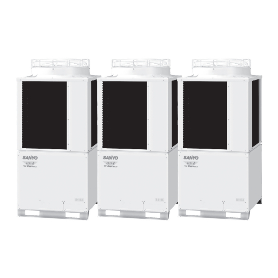
SPW-C0705DZH8
Sanyo SPW-C0705DZH8 Air Conditioner Manuals
Manuals and User Guides for Sanyo SPW-C0705DZH8 Air Conditioner. We have
1
Sanyo SPW-C0705DZH8 Air Conditioner manual available for free PDF download: Technical Data Manual
Sanyo SPW-C0705DZH8 Technical Data Manual (703 pages)
3-WAY ECO-i MULTI SYSTEM 5 series
Brand:
Sanyo
| Category:
Air Conditioner
| Size: 39.05 MB
Table of Contents
Indoor Unit
1
Outdoor Unit
1
Technical Data
1
Special Precautions
2
Check of Density Limit
3
Table of Contents
4
OUTLINE of 3-WAY ECO-I SYSTEM
5
Line-Up
6
Indoor Units
6
Section 1: OUTLINE of 3-WAY ECO-I SYSTEM
6
Outdoor Units
7
Combination of Outdoor Units
8
Features of 3-WAY ECO-I SYSTEM
8
System Example
8
Dimensions
9
Dimensions of Unit Combinations
9
Capacity Control
10
Realization of Smooth Capacity Control from
10
DESIGN of 3-WAY ECO-I SYSTEM
11
Indoor Unit
11
Indoor Air Intake Temp. °C (DB)
12
Model Selecting and Capacity Calculator
12
Operating Range
12
Section 2: DESIGN of 3-WAY ECO-I SYSTEM
12
Model Selecting and Capacity Calculator
13
Model Selection Procedure
13
Procedure for Selecting Models and Calculating Capacity
13
Design of Tubing Length
14
Additional Refrigerant Charge
15
Refrigerant Charge Amount at Shipment (for Outdoor Unit)
15
System Limitations
15
Main Tubing Size after Distribution (LB, LC...)
16
Size of Tubing (LO) between Outdoor Units
16
Tubing Size
16
Indoor Unit Tubing Connection
17
Outdoor Unit Tubing Connection Size
17
Refrigerant Tubing (Design Pressure Capability: 3.3 Mpa)
17
Required Copper Tubing Dimensions
17
Common Solenoid Valve Kit
18
Installation Standards
18
Relationship between A/C Units and the Refrigerant Tubing
18
When Adding Ball Valve for Outdoor Unit
18
Capacity Loss Caused by Differences in Tubing Diameters
19
Recommended Suction and Discharge Tubes Diameter (MM)
19
Straight Equivalent Length of Joints
19
Check of Limit Density
20
Total Amount of Refrigerant
20
Calculating the Actual Capacity of each Indoor Unit
21
Indoor Unit Capacity Correction Coefficients
21
Outdoor Unit Capacity Correction Coefficient
21
Cooling Capacity
22
Heating Capacity
22
Graph of Capacity Correction Coefficients
23
Graph of Outdoor Unit Capacity Characteristics (1 – (2))
23
Table of Correction Coefficients by Horsepower (1 – (1))
23
Graph of Indoor Unit Capacity Characteristics
24
Capacity Characteristics
25
Capacity Correction Graph According to Temperature Condition
25
Heating Capacity Correction Coefficients for Frost/Defrost Operation
25
Capacity Change Characteristics
26
Rated Performance Values
26
Table of Correction Coefficients by Horsepower (HP)
26
Outdoor Unit Changes
28
Preliminary Selection
28
Selection Conditions
28
System Design
28
Indoor Unit Changes
29
Increasing the Size of the Refrigerant Tubing
30
Sample Calculation for the System below
30
Additional Refrigerant Charge after Extension
31
Additional Refrigerant Charge before Extension
31
Checking of Limit Density
32
Header Joint System (Indoor)
33
Installing Distribution Joint
33
Tube Branching Methods (Horizontal Use)
33
Electrical Wiring
34
General Precautions on Wiring
34
Recommended Wire Length and Wire Diameter for Power Supply System
34
Wiring System Diagrams
35
Connecting Multiple Indoor Units to a Single Solenoid Valve Kit
37
Each Method (General) and Conditions
37
Necessity of Setting Changes by Combination of each Method
38
External Static Pressure
39
For Stranded Wiring
39
How to Connect Wiring to the Terminal
39
How to Set the External Static Pressure of each Type (US Type)
39
1-Way Semi-Concealed & Slim Type
40
Ceiling-Mounted Type
40
Concealed-Duct Type, 2-Way, 4-Way Semi-Concealed Type
40
Installation Instructions
40
Installation Space
41
Total Heat Exchanger with DX Coil
41
Installing the Outdoor Unit in Heavy Snow Areas
42
Precautions When Installing in Heavy Snow Areas
42
Shield for Horizontal Exhaust Discharge
42
3-Unit Installation
43
Dimensions of Wind Ducting
43
Reference Diagram for Air-Discharge Chamber (Field Supply)
43
Dimensions of Snow Ducting
44
Reference Diagram for Snow-Proof Vents (Field Supply)
44
Dimensions for Connections of each Part
45
Optional Distribution Joint Kits
45
Notes on Installation
47
Optional Solenoid Valve Kit
47
Specifications
47
How to Use Suspension Hook
48
Suspension Bolt (M10 or 3/8") (Field Supply)
48
Installing the Outdoor Unit
49
Transporting
49
Connect the Tubing
50
Prepare the Tubing
50
Refrigerant Tubing (Existing Tubing Can be Used.)
50
Routing the Tubing
50
Precautions for Brazing
51
Refrigerant Tube Port
51
Tightening Torque for each Cap
51
Control of 3-WA y ECO-I SYSTEM
53
1 Main Operating Functions
55
Main Operating Functions
55
Room Temperature Control
55
1 Main Operating Functions
55
Section 3: Control of 3-WAY ECO-I SYSTEM
55
Automatic Control for Heating and Cooling
56
2 Wireless Remote Controller
57
2 Wireless Remote Controller
57
Wireless Remote Controller
57
Optional Controller (Remote Controller)
57
Names and Functions
57
Installing Batteries
59
Setting the Current Time
59
Operation
59
Dry Operation
59
Timer Operation
60
Adjusting the Wind Direction
60
Using the Timer
60
Canceling a Timer Setting
60
Operating Multiple In/Outdoor Units Simultaneously
61
Using the Remote Control
61
For Best Results
61
Addresses
61
Setting Addresses (RCS-XM18BG.WL / K Types)
62
Emergency Operation
63
Miscellaneous Settings
64
Before Requesting Service
64
How to Install the Wireless Remote Controller Receiver
65
Warning about Installation of Receivers
65
Warning about Installing Remote Controls
65
Accessories
66
Installing the Receiver Unit
66
Refer to the Installation Manual Packed with the Panel
66
Wiring the Receiver Unit
67
Test Operation
67
Setting Address Switches
67
Wiring the Receiver
69
Wiring Diagram
69
Implementing a Test Run
70
Installing the Display/Operation Panel
71
Installing the Operation Panel
71
Installing the Display
71
The Self-Diagnosis Function Display and What Is Detected
79
Room Temperature Sensor Settings
79
When Using RCS-BH80BG.WL
79
Common to All Models
79
Setting up Remote Control Functions
80
Making Settings (Do with Unit Stopped)
80
Example: Operation Mode Setting Screen
80
Timer Remote Controller/Rcs-TM80BG
81
How to Use the Timer Remote Controller
81
Operating Buttons
81
Display
81
Names and Operations
82
Operation Section
82
Display Section
83
Setting the Present Time
84
Weekly Program Function
85
Checking Weekly Timer
85
Program Image Diagram
85
Changing the Program Timer
86
Deleting the Program Timer
88
Invalidating Program Timer
88
If Power Failure Occurred
88
Duplicating the Program Timer
89
Before Asking Repair Work
89
Outing Function
90
General Performance of the Outing Function
90
Setting the Outing Function
91
Canceling the Outing Function
91
Outing Function Indication
91
Sleeping Function
92
When the off Time Comes
92
To Cancel the Sleeping Function Operation
92
Check the Following Table
93
Installation Manual for Timer Remote Controller
94
How to Install the Remote Controller
94
Basic Wiring Diagram
94
Connection Diagram
94
4 System Controller
95
Remote Controller Setting Mode
95
Indoor Unit Setting Mode
95
To Display the Sensor Temperature
95
To Display the Trouble History
95
Group Control Using 2 Remote Controllers
95
Caution When Installing the Remote Controller
96
Meaning of Alarm Messages
97
Table of Self-Diagnostics Functions and Description of Alarm Displays
97
System Controller / SHA-KC64AGB
100
Operation Buttons
100
How to Start Group Operation
104
To Start Group Operation
104
How to Start Collective Operation
105
How to Install the System Controller
106
Installation Site Selection
106
Overview of the System Controller
107
Installation Procedure
108
Normal Mounting
108
Flush Mounting
108
Layout of Electrical Terminals
109
How to Connect Electrical Wiring
109
Basic Wiring
109
Terminals for Remote Monitoring
109
Address Switch Setting
111
Mode Setting
114
ALL Mode
114
ZONE Mode
114
How to Perform Zone Registration
115
Zone Registration Table
116
Zone Registration Using the Remote Controller
117
Zone Registration Using the System Controller (SHA-KC64AGB)
118
Automatic Zone Registration Using the System Controller (SHA-KC64AGB)
118
How to Check Overlapping of Central Address Nos.
119
Test Run
119
System Examples
120
Schedule Timer / SHA-TM64AGB
122
Using the Schedule Timer
123
Setting Today’s Day of the Week
125
Setting up Programmed Operations
126
Setting Errors
128
If Program Times Are the same
128
How to Check Program Times
129
How to Copy Program Times
130
How to Copy Day Programs
130
Example of Day Program Copying
130
Example of Group Program Copying
130
How to Copy Group Programs
132
How to Set Holidays in a Scheduled Week of Operation
134
Example Setting
134
How to Clear Programs
136
To Cancel Specific Days
136
To Cancel Individual Programs on Specific Days
136
Schedule Timer and Air Conditioner Operation
137
Schedule Timer Settings (Example)
137
Operation Without System Controller Operation
137
Operation with System Controller Operation
137
Power Outages
138
Accessories for Schedule Timer
140
Installing the Schedule Timer
140
Installation of Connected Schedule Timers
141
Wiring the Schedule Timer
141
Before Beginning Wiring
141
About the Setting Switches
143
Creating Timer Groups
144
Procedure for Making Fixed Timer Group Settings (Fixed Groups)
144
Procedure for Making Manual Timer Group Settings
144
Memory Backup Switch
145
Explanation to Customers
145
Installation Work Plan
146
Simplified Remote Controller / RCS-KR1EG
147
Moving and Repair Precautions
147
Precautions for Use
147
Simplifi Ed Remote Controller
147
Simplified Remote Controller
148
Basic Installation
151
Parts Supplied with Simplified Remote Controller
151
Simplified Remote Controller Installation Guidelines
151
How to Install the Simplified Remote Controller
151
How to Wire the Simplified Remote Controller
152
Guidelines for Using 2 Simplified Remote Controllers
152
Test Run Setting
154
Parts Supplied with Remote Sensor
155
Remote Sensor Installation Guidelines
155
Place of Installation
155
How to Install the Remote Sensor
156
How to Wire the Remote Sensor
157
How to Connect Lead Wires
157
3-Way Eco-I System Unit Specifications
159
Section 4: 3-WAY ECO-I SYSTEM UNIT SPECIFICATIONS
161
Unit Specifications
161
Outdoor Unit
161
Dimensional Data
179
Multiple Unit Installation Example
180
Refrigerant Flow Diagram
182
Noise Criterion Curves
184
4-Way Air Discharge Semi-Concealed Type (X, XM Types)
185
Air Flow Distance / Temperature Chart
236
Heating: Distribution of Wind Velocity
236
Heating: Distribution of Temperature
236
Cooling: Distribution of Wind Velocity
236
Cooling: Distribution of Temperature
237
Way Air Discharge Semi-Concealed Type (S Type)
242
Way Air Discharge Semi-Concealed Type (a Type)
258
Wall-Mounted Type (K Type)
267
Ceiling-Mounted Type (T Type)
291
Concealed Duct Type (U, US Types)
320
Concealed Duct Type (U, US Types)
444
Flange for Air Intake Duct (Field Supply)
451
Increasing the Fan Speed
455
Booster Cable for Concealed Duct Type
455
How to Read the Diagram
455
For Short Circuit Connection
456
For Wired Remote Control
456
Concealed Duct High Static Pressure Type (D Type)
457
Concealed Duct High Static Pressure Type (D Type)
467
Floor-Standing Type (F Type)
473
Concealed Floor-Standing Type (FM Type)
488
1-Way Air Discharge Semi-Concealed Slim Type (L Type)
504
Total Heat Exchanger with DX Coil (GU Type)
517
Intaking Fresh Air of Semi-Concealed Type and Concealed-Duct Type
526
Precautions Regarding External Air Intake
526
Arranging Ducts and Filters in the Field
526
Thermal Insulation for Ducts
526
X, XM Types
527
Section 5: TEST RUN
530
Preparing for Test Run
530
Test Run Procedure
531
Items to Check before the Test Run
531
Main Outdoor Unit PCB Setting
532
Examples of the No. of Indoor Units Settings (S005, S004)
533
Examples of the No. of Outdoor Units Settings (S006)
533
Address Setting of Main Outdoor Unit (S007)
533
Address Setting of Sub Outdoor Unit
533
Auto Address Setting
534
Automatic Address Setting from the Outdoor Unit
534
Automatic Address Setting (no Compressor Operation)
536
Automatic Address Setting from Outdoor Unit
536
Automatic Address Setting in Heating Mode
537
Display During Automatic Address Setting
539
On Outdoor Main Unit PCB
539
Remote Controller Display
539
Checking the Indoor Unit Addresses
540
Individual Control of Solenoid Valve Kit
540
Remote Controller Test Run Settings
541
Chart of Setting Change According to each Method
541
Caution for Pump down
541
Of Self-Diagnostics Functions and Description of Alarm Displays
542
Viewing the LED 1 and 2 (D72 and D75) Alarm Displays
542
Meaning of Alarm Messages
542
Electrical Data
545
Section 6: ELECTRICAL DATA
546
Electric Wiring Diagram SPW-C0705/0905/1155DZH8
546
Outdoor Unit
546
Schematic Diagram SPW-C0705/0905/1155DZH8
547
Electric Wiring Diagram SPW-C1305/1405DZH8
548
Schematic Diagram SPW-C1305/1405DZH8
549
Indoor Unit
550
Pcb and Functions
591
Section 7: PCB and FUNCTIONS
592
Outdoor Unit Control PCB
592
Functions (for CR-C1155DZH8)
593
2P Plug (White): Automatic Address Setting Pin
593
Indoor Unit Control PCB Switches and Functions
596
T10 Terminal Wiring Example
600
No Signal off Control
600
Control Items
600
Capacity Table
607
Section 8: CAPACITY TABLE
608
Capacity Ratio of Outdoor Unit
608
Capacity Table
609
Cooling Capacity of Indoor Unit
628
Advertisement
Advertisement
Related Products
Sanyo SPW-C0705DXHN8
Sanyo 2-WAY ECO-i SPW-C0705DXHN8R
Sanyo SPW-C0905DXHN8
Sanyo SPW-C0905DZH8
Sanyo 2-WAY ECO-i SPW-C0905DXHN8R
Sanyo SPW-C253GH8
Sanyo SPW-C256VH
Sanyo SPW-CR253GL5
Sanyo SPW-C483G8
Sanyo Bid Pack I SPW-C906VH8
Sanyo Categories
Projector
TV
Air Conditioner
Security Camera
LCD TV
More Sanyo Manuals
Login
Sign In
OR
Sign in with Facebook
Sign in with Google
Upload manual
Upload from disk
Upload from URL