Sign In
Upload
Manuals
Brands
Sanyo Manuals
Air Conditioner
SPW-CR365GX56
User Manuals: Sanyo SPW-CR365GX56 Air Conditioner
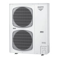
Manuals and User Guides for Sanyo SPW-CR365GX56 Air Conditioner. We have
2
Sanyo SPW-CR365GX56 Air Conditioner manuals available for free PDF download: Technical Data Manual, Installation Instructions Manual
Sanyo SPW-CR365GX56 Technical Data Manual (346 pages)
MINI ECO-i SYSTEM
Brand:
Sanyo
| Category:
Air Conditioner
| Size: 16.49 MB
Table of Contents
Technical Data
1
Read before Starting
2
Special Precautions
2
Check of Density Limit
3
Table of Contents
4
Outline of Mini Eco-I System Contents
5
Indoor Units
6
Line-Up
6
Outdoor Units
7
Design of Mini Eco-I System Contents
9
Model Selecting and Capacity Calculator
10
Operating Range
10
Procedure for Selecting Models and Calculating Capacity
11
Calculating the Corrected Capacities for the Outdoor Unit and each Indoor Unit
12
Calculation of Actual Capacity of Indoor Unit
12
Indoor Unit Capacity Correction Coefficients
12
Outdoor Unit Capacity Correction Coefficient
12
Calculating the Actual Indoor Unit Capacity Based on the Indoor/Outdoor Corrected Capacity Ratio
13
Graph of Capacity Correction Coefficients
14
Outdoor Unit Cooling Capacity Characteristics
14
Outdoor Unit Heating Capacity Characteristics
15
Capacity Correction Graph According to Temperature Condition
17
Cooling
17
Heating
18
Capacity Correction Graph According to Tubing Length and Elevation Difference
19
Inverter Model Rated Performance Values
19
For CR365, 485GX(H)56 Units
20
Accessories Supplied with Outdoor Unit
21
Electrical Wiring for Details
21
System Design
21
Tools Required for Installation (Not Supplied)
21
Straight Equivalent Length of Joints
22
Tubing Size
22
Additional Refrigerant Charge
23
System Limitations
23
Tubing Length
23
Check of Limit Density
24
Outdoor Unit Changes
25
Preliminary Selection
25
Selection Conditions
25
System Example
25
Additional Refrigerant Charging
27
Example of Tubing Size Selection and Refrigerant Charge Amount
27
Checking of Limit Density
28
Installing Distribution Joint
29
Tube Branching Methods (Horizontal Use)
29
Type
29
Optional Ball Valve Kit
30
Optional Distribution Joint Kit
30
Ball Valve Installation (for Refrigerant R410A Only)
31
Dimensions
31
Flare Nut Tightening
31
Installing the Ball Valve
31
Installing Thermal Insulation
32
Opening and Closing the Valve
32
Recommended Location of Ball Valves
32
When Adding Ball Valve for Indoor Unit
32
Installation Instructions
33
In Case of Multiple Installations
34
Installation Space
34
Air Discharge Chamber for Top Discharge
35
Installing the Unit in Heavy Snow Areas
35
Precautions for Installation in Heavy Snow Areas
35
Dimensions of Air-Discharge Chamber Reference Diagram for Air-Discharge Chamber (Field Supply) STK-DRE140A for SPW-CR365/485/605GX(H)56(A/B)
36
Dimensions of Outdoor Unit with Air-Discharge Chamber (Field Supply) SPW-CR365/485/605GX(H)56(A/B) with STK-DRE140A
36
Dimensions of Outdoor Unit with Snow-Proof Vents (Field Supply) SPW-CR365/485/605GX(H)56(A/B) with STK-BDR140U
38
Dimensions of Snow Ducting Reference Diagram for Snow-Proof Vents (Field Supply) STK-BDR140U for SPW-CR365/485/605GX(H)56(A/B)
38
Reference Diagram for Snow-Proof Vents
40
Space Requirements for Setting – SPW-CR365/485/605GX(H)56(A/B) with STK-BDR140U
40
Drainage Work
41
Installing the Outdoor Unit
41
Routing the Tubing and Wiring
41
Electrical Wiring
42
General Precautions on Wiring
42
Recommended Wire Length and Wire Diameter for Power Supply System
42
Wiring System Diagram (for Single-Phase Outdoor Unit)
43
(For 3-Phase Outdoor Unit)
44
How to Connect Wiring to the Terminal
46
Control of Mini Eco-I System Contents
47
Main Operating Functions
49
Room Temperature Control
49
Automatic Control for Heating and Cooling
50
I How to Use the Wireless Remote Controller
51
Optional Controller (Remote Controller)
51
I Receiver
54
How to Install the Wireless Remote Controller Receiver
55
I RCS-SH80AG.WL for 4-Way Cassette (X Type)
55
Accessories
56
Precautions on Simultaneous Installation of Wired Remote Controller and Wireless Remote Controller
56
Wiring the Receiver Unit
56
How to Use the Test Run Setting
57
I RCS-TRP80ANG.WL for Ceiling Mounted (T, LD Type)
58
Installing the Receiver Unit
58
For 1-Way Air Discharge High-Ceiling Cassette Type (LD Type)
59
Accessories Supplied with Unit
60
When 1 Indoor Unit Is Operated with 2 Remote Controllers
61
When Several Groups of Indoor Units Are Operated with 2 Remote Controllers
61
I RCS-TH80AG.WL for 2-Way Type (S Type)
62
Installing the Control Unit
62
Installing the Display
62
Accessories Supplied with Separate Receiver Unit
66
How to Install the Separate Receiver Unit
66
I RCS-BH80AG.WL for AS, U, D, F, FM Type
66
Important Information for Installation of 1 Separate Receiver Unit
66
Wiring the Separate Receiver Unit
69
Important Information for Installation of 2 Separate Receiver Units
70
I How to Use the Wired Remote Controller
72
Wired Remote Control / RCS-SH80AG
72
I Display
75
I Setting the Timer
76
Canceling Timer Operation
77
How to Set the off Cycle Timer
77
How to Set the off Timer
77
How to Set the on Timer
77
Accessories for Remote Controller Switch
78
Diagram of Outer Dimensions
78
I How to Install the Remote Controller
78
When Using a Wall Box for Flush Mounting
78
Group Control Using 2 Remote Controllers
79
I Basic Wiring Diagram
79
I Wiring System Diagram for Group Control
79
Wiring Procedure
79
Cautions on Group Control
80
Group Control Within the same Refrigerant Tub-Ing System Is Recommended
80
Setting the Main and Sub Remote Controllers
80
I Connecting to a Ventilation Fan
81
I Switching the Room Temperature Sensors
81
I Wiring the Remote Controller
82
I Meaning of Alarm Messages
83
Table of Self-Diagnostics Functions and Description of Alarm Displays
83
I Operation Buttons
85
System Controller / SHA-KC64AG
85
I Display
88
I How to Start Group Operation
89
I How to Start Collective Operation
90
I How to Install the System Controller
91
Installation Site Selection
91
I Overview of the System Controller
92
I Installation Procedure
93
How to Connect Electrical Wiring
94
I Layout of Electrical Terminals
94
I Basic Wiring Diagram
95
How to Reach the PCB
96
I Address Switch Setting
96
Sw1
97
Sw2
98
I Mode Setting
99
I How to Perform Zone Registration
100
I Zone Registration Table
101
Zone Registration Using the Remote Controller (RCS-SH80AG)
102
Automatic Zone Registration Using the System Controller (SHA-KC64AG)
103
Zone Registration Using the System Controller (SHA-KC64AG)
103
I How to Check Overlapping of Central Address Nos
104
I Memory Back-Up Switch
104
I Test Run
104
For a System Without Link
105
I System Examples
105
For a System with Link
106
I Operation Buttons
107
Schedule Timer / SHA-TM64AG
107
I Display
108
I Using the Schedule Timer
108
I Setting the Present Time
109
I Setting Today's Day of the Week
110
I Setting up Programmed Operations
111
Example of Time Settings that Do Not Cause Errors
113
I Setting Errors
113
If Program Times Are the same
113
I How to Check Program Times
114
I How to Copy Program Times
115
I How to Copy Group Programs
117
I How to Set Holidays in a Scheduled Week of Operation
119
I How to Clear Programs
121
I Schedule Timer and Air Conditioner Operation
122
Operation with System Controller Operation
122
Operation Without System Controller Operation
122
Schedule Timer Settings (Example)
122
I Power Outages
123
Operation When Power Is Lost at 15:00 and Subsequently Restored
123
Operation When Power Is Not Lost
123
I Troubleshooting
124
I Accessories for Schedule Timer
125
I Installing the Schedule Timer
125
I Installation of Connected Schedule Timers
126
I Wiring the Schedule Timer
126
Connection Diagram
127
If a System Controller Is also Installed
127
If a System Controller Is Not Installed
127
Wiring
127
I about the Setting Switches
128
I Creating Timer Groups
129
Procedure for Making Fixed Timer Group Settings (Fixed Groups)
129
Procedure for Making Manual Timer Group Settings (Manual Group Assignments)
129
I Checking the Central Control Addresses and Operating the Units that Are Controlled by the Schedule Timer
130
I Explanation to Customers
130
I Memory Back-Up Switch
130
I Installation Work Plan
131
I Operation Buttons
132
Simplified Remote Controller / RCS-KR1AG
132
Description
134
I Display
134
I Operation
135
I Tips for Energy Saving
136
I Troubleshooting
136
I How to Install the Simplified Remote Controller
137
I Simplified Remote Controller Installation Guidelines
137
Place of Installation
137
How to Connect Lead Wires
138
I How to Wire the Simplified Remote Controller
138
I Guidelines for Using 2 Simplified Remote Controllers
139
I Remote Controller Test Run Setting
139
Set-Up Procedure
139
I Parts Supplied with Remote Sensor
140
I Remote Sensor Installation Guidelines
140
Remote Sensor / ART-K45AG
140
I How to Install the Remote Sensor
141
I How to Wire the Remote Sensor
142
I Important Information When Using Together with Remote Controller Switch
142
Mini ECO-I SYSTEM Unit Specifications Contents
143
Outdoor Unit
145
Unit Specifications
145
Major Component Specifications
154
Dimensional Data
163
Refrigerant Flow Diagram
164
Sound Data
165
Sound Power Level
165
Sound Pressure Level
167
4-Way Air-Discharge Semi-Concealed Type (X Type)
169
Noise Criterion Curves SPW-XDR***GXH56(A/B)
189
Air Throw Distance Chart SPW-XDR***GXH56(A/B)
190
2-Way Air Discharge Semi-Concealed Type (S Type)
191
Indoor Unit: 25 Type
204
Noise Criterion Curves SPW-SR***GXH56(A/B)
205
Air Throw Distance Chart
206
1-Way Air Discharge Semi-Concealed Type (as Type)
207
Noise Criterion Curves
214
Air Throw Distance Chart SPW-ASR**4GXH56(A/B)
215
Wall-Mounted Type (K Type)
216
Noise Criterion Curves SPW-KR***GXH56(A/B)
229
Air Throw Distance Chart SPW-KR***GXH56(A/B)
230
Ceiling-Mounted Type (T Type)
231
Noise Criterion Curves SPW-TDR***GXH56(A/B)
244
Air Throw Distance Chart SPW-TDR***GXH56(A/B)
245
Concealed Duct Type (U Type)
246
Dimensional Data Indoor Unit : 7, 9, 12, 16, 18 Type
262
Dimensional Data Indoor Unit : 25 Type
263
Dimensional Data Indoor Unit : 36, 48 Type
264
Flange for Air Intake Duct (Field Supply) for Concealed Duct Type
265
Increasing the Fan Speed
268
Indoor Fan Performance
268
Concealed Duct High Static Pressure Type (D Type)
269
Dimensional Data Indoor Unit : 25, 36, 48 Type
275
How to Read the Diagram
277
Floor-Standing Type (F Type)
278
Dimensional Data Indoor Unit: 9, 12, 16, 18, 25 Type
290
Concealed Floor-Standing Type (FM Type)
293
Dimensional Data Indoor Unit: 7, 9, 12, 16, 18, 25 Type
305
1-Way Air Discharge Semi-Concealed Slim Type (LD Type)
309
Air Purging
323
Test Run and Others Contents
323
Air Purging
324
Air Purging with a Vacuum Pump (for Test Run) Preparation
324
Leak Test
324
Manifold Gauge
324
Evacuation
325
Required Time for Evacuation When 30 Gal/H Vacuum Pump Is Used
325
Charging Additional Refrigerant
326
Finishing the Job
326
Check Points before Attempting to Start the Air Conditioner
327
Preparing for Test Run
327
Items to Check before the Test Run
328
Test Run Procedure
328
Outdoor Unit PCB Setting (for SPW-CR *** GX(H)56)
329
Outdoor Unit PCB Setting (for SPW-CR *** GX(H)8)
330
Examples of Refrigerant Circuit (R.C.) Address Settings
331
Examples of the No. of Indoor Units Settings
331
Auto Address Setting
332
Automatic Address Setting from the Outdoor Unit
332
Automatic Address Setting (no Compressor Operation)
334
Automatic Address Setting from Outdoor Unit
334
Automatic Address Setting in Heating Mode
335
Automatic Address Setting in Cooling Mode
336
Display During Automatic Address Setting
337
Checking the Indoor Unit Addresses
338
If 1 Indoor Unit Is Connected to 1 Remote Controller
338
Remote Controller Test Run Settings
338
Request Concerning Recording the Indoor/Outdoor Unit Combination Nos
338
Caution for Pump down
339
Meaning of Alarm Messages
339
Check of Density Limit
341
Installation Standards
341
Be Sure to Recharge the Refrigerant Only in Liquid Form
342
Care Regarding Tubing
342
Different Tools Required
342
Precautions for Installation Using New Refrigerant
342
Single-Outlet Valve
343
Advertisement
Sanyo SPW-CR365GX56 Installation Instructions Manual (49 pages)
System Air Conditioner
Brand:
Sanyo
| Category:
Air Conditioner
| Size: 4.3 MB
Table of Contents
Important
2
Please Read before Starting
2
Check of Density Limit
3
Precautions for Installation Using New Refrigerant
4
Table of Contents
6
General
7
Tools Required for Installation (Not Supplied)
7
Type of Copper Tube and Insulation Material
7
Additional Materials Required for Installation
7
Tubing Size
8
Straight Equivalent Length of Joints
9
Additional Refrigerant Charge
9
System Limitations
9
Tubing Length
10
Check of Limit Density
11
Installing Distribution Joint
11
Optional Distribution Joint Kit
12
Optional Ball Valve Kit
12
Recommended Location of Ball Valves
14
Example of Tubing Size Selection and Refrigerant Charge Amount
15
Selecting the Installation Site
17
Indoor Unit
17
Outdoor Unit
18
Air-Discharge Chamber for Top Discharge
19
Installing the Unit in Heavy Snow Areas
19
Precautions for Installation in Heavy Snow Areas
19
Dimensions of Air-Discharge Chamber
20
Dimensions of Outdoor Unit with Air-Discharge Chamber (Field Supply)
20
Dimensions of Snow Ducting
22
Dimensions of Outdoor Unit with Snow-Proof Vents (Field Supply)
22
How to Install the Outdoor Unit
25
Installing the Outdoor Unit
25
Drainage Work
25
Routing the Tubing and Wiring
25
Electrical Wiring
26
General Precautions on Wiring
26
Recommended Wire Length and Wire Diameter for Power Supply System
26
Wiring System Diagrams
27
How to Process Tubing
30
Connecting the Refrigerant Tubing
30
Connecting Tubing between Indoor and Outdoor Units
31
Insulating the Refrigerant Tubing
32
Taping the Tubes
33
Finishing the Installation
33
Air Purging
34
Air Purging with a Vacuum Pump (for Test Run) Preparation
34
Test Run
37
Preparing for Test Run
37
Test Run Procedure
38
Auto Address Setting
41
Caution for Pump down
48
Meaning of Alarm Messages
48
Advertisement
Related Products
Sanyo ECOi SPW-CR365GXH56B
Sanyo ECOi SPW-CR365GXH8B
Sanyo SPW-CR365GXH56
Sanyo SPW-CR365GXH8
Sanyo MINI ECO-i SPW-CR365GX56B
Sanyo SPW-CR364GVH56-C
Sanyo SPW-CR364GV56-C
Sanyo SPW-CR363GVH8
Sanyo SPW-CR363GV8
Sanyo SPW-CR363GHL8
Sanyo Categories
Projector
TV
Air Conditioner
Security Camera
LCD TV
More Sanyo Manuals
Login
Sign In
OR
Sign in with Facebook
Sign in with Google
Upload manual
Upload from disk
Upload from URL