Sign In
Upload
Manuals
Brands
Siemens Manuals
Switch
3KC8
Siemens 3KC8 Manuals
Manuals and User Guides for Siemens 3KC8. We have
1
Siemens 3KC8 manual available for free PDF download: Manual
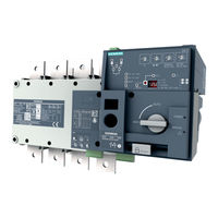
Siemens 3KC8 Manual (224 pages)
Transfer Switching Equipment and Load Transfer Switches
Brand:
Siemens
| Category:
Switch
| Size: 22.82 MB
Table of Contents
Legal Information
4
Table of Contents
5
1 Introduction
9
2 General Information
11
Certification
11
3 Product Information
13
Product Description
13
Design of the 3KC4 and 3KC8 Transfer Switching Equipment
14
Current Ratings of the 3KC4 and 3KC8 Transfer Switching Equipment
18
Product Family
21
The Product Families 3KC4 and 3KC8 from 250 a to 3200 a
21
Use of 3KC4 and 3KC8 Transfer Switching Equipment
22
Properties of the 3KC4 and 3KC8 Transfer Switching Equipment
22
Application Areas of the 3KC4 and 3KC8 Transfer Switching Equipment
23
4 Functions
25
5 Mounting
27
Mounting Position
27
Installing the 3KC4 and 3KC8 Transfer Switching Equipment
27
Dimensions of the Cover Frame for Door Cut-Out
30
6 Connection
31
Network Types
31
Three-Phase 4-Wire Network with Neutral (3PH + N)
32
Circuit Diagram for the 3KC4 Transfer Switching Equipment - 4-Pole Transfer Switching Equipment
32
Circuit Diagram for the 3KC8 Transfer Switching Equipment - 4-Pole Transfer Switching Equipment
33
Three-Phase 3-Wire Network Without Neutral (3PH)
33
Equipment
34
Circuit Diagram for the 3KC8 Transfer Switching Equipment - 4-Pole Transfer Switching
35
Equipment
35
Circuit Diagram for the 3KC8 Transfer Switching Equipment - 3-Pole Transfer Switching Equipment
36
Single-Phase Network with Neutral (1PH + N)
37
Circuit Diagram for the 3KC4 Transfer Switching Equipment - 3-Pole Transfer Switching
37
Equipment
37
Circuit Diagram for the 3KC8 Transfer Switching Equipment - 3-Pole Transfer Switching
38
Equipment
38
Connecting the Main Circuit
39
Connecting Terminals of the Transfer Switching Equipment
39
Load Connection
40
Arrangement of the Power Supply Systems
40
Connection of Transfer Switching Equipment for Current Ratings 250 a to 1600 a
42
Connecting Bridging Bars on the Load Side
42
Connecting Current Ratings 250 a to 1600 a to the Main Circuit
46
Connection of Transfer Switching Equipment for Current Ratings 2000 a to 3200 a
49
Copper Bar Connection Kit
49
Connecting Current Ratings 2000 a to 3200 a to the Main Circuit (on the Line Side)
55
Connecting Current Ratings 2000 a to 3200 a to the Main Circuit (on the Load Side)
65
Connecting the Control Circuit
72
Inputs and Outputs of the Motor Operator
72
Overview of Motor Operator
72
Connecting the Inputs and Outputs of the Motor Operator
73
Power Supply of the Motor Operator (3KC4 Only)
75
Mounting and Connecting the Dual Power Supply (DPS)
77
Installing and Connecting an Autotransformer (400 V / 230 V)
79
Auxiliary Switch of the Transfer Switching Equipment
81
Installing Auxiliary Switches 250 a to 630 a
82
Installing Auxiliary Switches of Current Rating 800 a to 1600 a
84
Inputs and Outputs of the Electronic Module (3KC8 Only)
88
Connecting the Inputs and Outputs of the Electronic Module (3KC8 Only)
89
Installing Accessories for the Electronic Module
89
Connecting Power Supply Kit 3KC9830-, 3KC9831- (4-Pole)
92
Connecting the Auxiliary Conductor Terminal 3KC9822-, 3KC9832- for a Three-Phase 3-Wire Network (3-Pole)
95
Connecting Power Supply Kit 3KC9833-, 3KC9834- for Single-Phase Network
98
7 Operation
101
Operating Modes of the Transfer Switching Equipment
101
Remote Mode
102
Manual Operation
103
Padlocking Mode
104
Automatic Mode (3KC8 Only)
105
Functions of the Inputs and Outputs
106
Inputs and Outputs of the Motor Operator
106
Outputs of the Motor Operator
111
Auxiliary Switches
114
Inputs and Outputs of the Electronic Module (3KC8 Only)
115
Inputs for Voltage Measurement and Power Supply
115
Control Inputs of the Electronic Module
118
Functions of the Control Inputs for Network / Generator Application
119
Functions of the Control Inputs for Network / Network Application
121
Outputs of the Electronic Module
123
Remote Mode
126
Impulse Logic
126
Continuous Operation Logic
129
Automatic Mode - Programming of the Electronic Module (3KC8 Only)
132
Step 1: Preset Network Conditions
132
Step 2: Setting the Potentiometer
134
Step 3: Automatic Configuration of the Transfer Switching Equipment (Only with Potentiometer un = 0)
136
Step 4: Saving the Configuration
137
Step 5: Switching the 3KC8 Transfer Switching Equipment to Automatic Mode
137
8 Commissioning
139
Commissioning the 3KC4 Transfer Switching Equipment
139
Commissioning the 3KC8 Transfer Switching Equipment
141
9 Accessories
145
Terminal Covers
146
Mounting Terminal Covers
147
Phase Barriers
148
Mounting Phase Barriers
149
Terminal Plates
150
Mounting Terminal Plates
151
Mounting Spacers
153
Fitting Mounting Spacers
153
Bridging Bars
154
Copper Bar Connection Kit
155
Autotransformer
157
Dual Power Supply (DPS, 3KC4 Only)
158
Power Supply Kit 3KC9830-, 3KC9831- (4-Pole, 3KC8 Only)
159
Auxiliary Conductor Terminal 3KC9822-, 3KC9832- (3-Pole, 3KC8 Only)
160
Power Supply Kit 3KC9833-, 3KC9834- (2-Pole, 3KC8 Only)
161
Cover Frame (3KC8 Only)
162
Auxiliary Switches
163
Display (3KC8 Only)
164
Connection Cable (3KC8 Only)
167
Sealable Cover (3KC8 Only)
168
Motor Operator
170
Electronic Module (3KC8 Only)
175
10 Service and Maintenance
177
Fault Rectification
177
Fault States and Fault Detection on the 3KC4 Transfer Switching Equipment
177
Fault States and Fault Detection on the 3KC8 Transfer Switching Equipment
179
Regular Service and Maintenance
181
11 Technical Specifications
183
Technical Specifications 3KC4 and 3KC8 from 250 a to 1000 a
183
Technical Specifications 3KC4 and 3KC8 from 1250 a to 3200 a
186
Technical Specifications of the Electronic Module
189
12 Dimension Drawings
191
Dimension Drawings of the 3KC4 Transfer Switching Equipment
192
Dimension Drawings of the 3KC8 Transfer Switching Equipment
198
13 Applications
205
Transfer between Two Sources with One Outgoing Load
206
Transfer between Two Sources with Two Outgoing Loads
207
Transfer between Three Sources with One Outgoing Load
209
Transfer between Three Sources with Two Outgoing Loads
210
Transfer between Two Loads with One Incoming Source (with 3KC4 Transfer Switching Equipment Only)
213
Appendix
215
Environmental Conditions
215
A.1 Environmental Conditions
215
Operating Conditions
216
Temperature
216
Humidity
216
Altitude Conditions
216
A.2 Operating Conditions
216
Storage Conditions
217
Temperature
217
Storage Position
217
A Appendix
217
ESD Guidelines
221
Electrostatic Sensitive Devices (ESD)
221
List of Abbreviations
223
Advertisement
Advertisement
Related Products
Siemens 3KC8348 - 0FA22 - 0GA3
Siemens 3KC8352 - 0GA22 - 0GA3
Siemens 3KC8456 - 0JA22 - 0GA3
Siemens 3KC8448 - 0FA22 - 0GA3
Siemens 3KC8452 - 0GA22 - 0GA3
Siemens 3KC8358 - 0JA22 - 0GA3
Siemens 3KC8350 - 0FA22 - 0GA3
Siemens 3KC8354 - 0HA22 - 0GA3
Siemens 3KC8458 - 0JA22 - 0GA3
Siemens 3KC8450 - 0FA22 - 0GA3
Siemens Categories
Industrial Equipment
Controller
Control Unit
Oven
Washer
More Siemens Manuals
Login
Sign In
OR
Sign in with Facebook
Sign in with Google
Upload manual
Upload from disk
Upload from URL