Sign In
Upload
Manuals
Brands
Siemens Manuals
Fire Alarms
FC700A
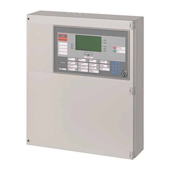
Siemens FC700A Manuals
Manuals and User Guides for Siemens FC700A. We have
4
Siemens FC700A manuals available for free PDF download: Hardware Description, System Planning Manual, Installation And Hardware Commissioning, Maintenance Instructions Manual
Siemens FC700A System Planning Manual (70 pages)
Fire detection system
Brand:
Siemens
| Category:
Fire Alarms
| Size: 2.18 MB
Table of Contents
Table of Contents
3
1 About this Document
6
2 Safety Regulations
8
Signal Words and Symbols
8
Signal Words and Their Meaning
8
Symbols and Their Meaning
8
Classification and Meaning of Additional Symbols
9
Safety-Relevant Working Instructions
9
3 Main Features
11
4 Technical Data FC700A
12
5 Logical and Physical Structure
13
6 Bus Systems
14
Bus Overview
15
Modifying the Impedance of the Various C-Bus Cables
15
Diagram
16
7 Bus Stations
17
Station
17
Types of Stations
17
Hardware
17
Visualizer for Windows Remote Operation Software (Not Available Yet)
18
Logical AREAS
19
8 Limitations of C-Bus Participants
20
Main CPU Limits
20
Maximum Number of Devices
20
Limits in the Logical Structure
20
Maximum Number of Criteria in Zones Control 4 and 6
20
Maximum Number of ZONE Time Channel
20
Maximum Number of I-Bus-Modules
21
Limits of 5V Supply
21
Control Terminal Limits (FC/FT)
21
Limitation of Visible Texts on a FC700A
21
Limitation of Visible Texts on a FT700A
21
Gateway Limits (FG)
22
9 Specify Hardware Required
23
10 Control Unit FC700A
24
Configuration
24
Block Diagram
25
Modules
25
11 Auxiliary Power Supply
26
Configuration
26
Block Diagram
26
Modules
26
12 Control Terminal B3Q700 (FC/FT)
27
Features
27
Options
27
Plexiglas Door to B3Q700 (FC/FT)
27
Place of the E3I020 RS232 Module (FT)
28
Place of the E3I040 LON Interface (FT)
28
Installation Possibilities (FT)
29
Block Diagram
29
Connection Lines between Control Unit and External Operating Units
30
Power Supply (24V)
30
Modules
31
13 Range of Cabinets H23 / H26 / H28
33
Recessed Mounting H23G230 and H28G200
33
Modules
33
19 " Accessories
34
Modules
34
15 Line Modules
35
Overview
35
Modules
35
Detection Line "Addressable" Synoloop
36
Detection Line "Collective" Synoline600/-Ex
37
16 Connection Factors, Line Resistances and Capacitances
38
Terminology and Abbreviations
38
Collective Detection Line
38
Addressable Detection Line
38
Line Resistance and Capacitance
39
17 Control Modules
40
Application of Control Modules
40
17.1.1 Overview of the Available Modules with Control Outputs
40
Means of Linking
40
Control Outputs Station Type FC700A
41
Control Outputs Remote Station Type FT700A
41
Modules
41
CPU-Overlapping Controls
42
MIMIC Display Panel Outputs
43
Modules
43
Relay Outputs
44
17.10 Modules
44
18 LON-Bus Devices
45
Features
45
LON-Bus as Stub Line
45
LON-Bus as Free Topology
46
Lon/MIMIC Display P.C.b K3I050
46
LON I/O Card K3I110
46
Indicator Devices B3Q580 and B3Q590/595
47
Modules
47
19 Gateway
48
Main Features
48
Application
48
Modules
49
20 Remote Transmission
50
21 Printer Interface
51
Features
51
Application Variant FT
51
Application Variant FC
51
Modules
51
22 Power Supply
52
Concept
52
Special Functions
52
Application
52
Power Supply for the Control Unit
52
Auxiliary Power Supply
52
Modules
53
Operation with Power Supply from Control Unit
53
Power Supply for Remote Transmission Equipment and Accessories
53
23 Emergency Power Supply
54
Specifying Battery Capacity
54
23.1.1 Battery Rated Capacity
54
23.1.2 Ageing of Battery
54
23.1.3 Calculation
54
Capacity Values for Standard Configurations
54
Quiescent Current Table
55
24 Alarm Concept
56
Cerberus Alarm Concept (CAC)
56
Principle of the Cerberus Alarm Concept
56
Determine the Alarm Organization
57
Organization of System Operation
57
25 Commissioning
58
26 Parameterization, Flash Programming
59
Functions
59
Modules
59
27 FC700A Modules in Alphabetical Order
60
28 Spare Parts
62
29 Configuration Sheets
63
List of Configuration Sheets
63
30 Control Unit FC700A
64
31 Auxiliary Power Supply
65
32 Control Terminal FT700A
66
33 Display & Operating Terminals
67
34 Externally Placed Modules
68
Advertisement
Siemens FC700A Hardware Description (108 pages)
Fire detection system
Brand:
Siemens
| Category:
Fire Alarms
| Size: 2.53 MB
Table of Contents
Table of Contents
3
1 About this Document
7
2 Safety Regulations
9
Classification and Meaning of Additional Symbols
10
3 Hardware Overview
12
4 Emergency Operation
16
Emergency Operation at Line Module E3M111 Level
17
5 Principle of 24V Wiring
19
Cascading Principle
20
6 Ground Fault Monitoring (FM Compliance)
21
Programming Ground Fault Monitoring
22
7 E3C011 Battery Charging Module
23
Important Components
24
Programming Switch "S3
25
LED Indicator Block "Battery-Charger
27
Connections
28
8 B2F020 Converter
29
Important Components
30
Connections
31
E3M080 Line Module "Collective
32
9 E3M080 Line Module ”Collective”
33
Line Voltage
33
Important Components
34
Connections
35
Connection "Collective" Synoline600/-Ex
36
E3M111 Line Module "Synoloop
37
Important Components
38
Connections
39
Connection "Addressable" Synoloop
40
Connection "Conventional" Synoline300
41
Connection "Collective" Synoline600
42
Connection "Collective" Synoline600-Ex
43
11 E3I040 I-Bus/Lon Module
44
Wiring Principle
45
Important Components
46
Connections
47
12 E3I020 RS232 Module
48
Wiring Principle
49
Important Components
50
13 E3H020 C-Bus Gateway
51
Wiring Principle
52
Important Components
53
Programming Switches "S1" + "S2
54
Connections
55
E3L020 Control Module "I/O
57
Important Components
58
Connections
59
15 E3L030 Control Module Vds
60
Important Components
61
Programming Switch "S3
62
Connections
63
E3G050 Control Module "Contacts
64
Important Components
65
Connections
66
E3G060 Control Module "Monitored
67
Important Components
68
Programming Switches "S7" & "S8
69
Connections
70
E3G070 Control Module "Universal
71
Important Components
72
Connections
73
19 Z3B171 Relay Module
74
20 B3Q700 Control Terminal to FC/FT
75
Application
76
Mechanical Design
77
Important Components
78
Programming Switch 'S5
79
Connectors
80
21 B3R051 Parallel Indicator Panel
81
Wiring Principle
82
Mechanical Design
83
Programming Switch "S1
84
22 K3R072 MIMIC Display Board
85
Wiring Principle
86
Important Components
87
Connections
88
23 K3G060 Relay Card
89
Mechanical Design
90
Connections
91
24 K3I050 MIMIC Display Converter
92
Mechanical Design
93
Programming Switch "S3
94
Connections
95
25 K3I110 LON I/O P.C.b
96
Mechanical Design
97
Programming Switch 'S3
98
Connections
99
B3Q580 Floor Repeater Panel and B3Q590/B3Q595 Floor Repeater Panel with Control Functions
100
Mechanical Design
101
Programming Switch "S3
102
Message Presentation
103
Country Specific Configuration Data
104
Connections B3Q580
107
Siemens FC700A Installation And Hardware Commissioning (38 pages)
Fire detection system
Brand:
Siemens
| Category:
Measuring Instruments
| Size: 1.38 MB
Table of Contents
Table of Contents
3
1 About this Document
5
2 Safety Regulations
7
Signal Words and Symbols
7
Signal Words and Their Meaning
7
Symbols and Their Meaning
7
Classification and Meaning of Additional Symbols
8
Safety-Relevant Working Instructions
8
3 Installation
10
Space for Parallel Indicator Panel
10
Housing Installation
11
Protection of the Installed Housing
12
4 Commissioning
13
Commissioning the System
13
Preparation
14
Programming the System
14
5 Installation of Hardware
15
Installation of Auxiliary P.C.b. Chassis
15
6 B3Q700 Control Terminal for Use as 'FC' or 'FT
16
7 Line Modules
17
E3M080 Line Module "Collective
17
E3M111 Line Module "Synoloop
17
8 LON Module
18
E3I040 I-Bus/Lon Module
18
9 Control Modules
19
E3L020 Control Module 'I/O
19
E3L030 Control Module 'Vds
19
E3G050 Control Module 'Contacts
20
E3G060 Control Module 'Monitored
20
E3G070 Control Module 'Universal
21
10 Control Terminal and Floor Repeater Panels
22
FT700A (B3Q700) Control Terminal
22
B3R051 Parallel Indicator Panel
22
K3R072 Synoptic P.C.b
22
K3G060 Relay P.C.b
23
K3I050 Lon/Synoptic P.C.b
23
K3I110 LON I/O P.C.b
24
B3Q580 Floor Repeater Panel
24
B3Q590/595 Floor Repeater Panel with Control Functions
25
11 Printer
26
E3I020 RS232 Module
26
12 Gateway FG700A
27
E3H020 C-Bus Gateway
27
E3H021 C-Bus Gateway
28
13 Power Supply
29
B2F020 Converter
29
E3C011 Battery Charging Module
29
14 Ground Fault Monitoring
30
Modules with Ground Fault Monitoring
30
14.1.1 Settings of the Modules in the Factory
30
Test Ground Fault Monitoring
30
15 Install Modules
31
16 Connection Periphery
32
17 First Switch-On
33
Battery Charging Module E3C011
33
Control Terminal B3Q700 ('FC'/'FT')
33
18 Read in
34
Read in of the Hardware Modules
34
Read in of Devices on a Loop
34
19 Device Activation for Testing/Upgrading a System
35
Automatic Detectors
35
Manual Call Points
35
Input/Output Modules
36
Advertisement
Siemens FC700A Maintenance Instructions Manual (20 pages)
Fire detection system
Brand:
Siemens
| Category:
Security System
| Size: 0.14 MB
Table of Contents
Table of Contents
3
1 About this Document
5
2 Safety Regulations
7
Signal Words and Symbols
7
Signal Words and Their Meaning
7
Symbols and Their Meaning
7
Classification and Meaning of Additional Symbols
8
Safety-Relevant Working Instructions
8
3 Test and Measuring Equipment
10
4 Preparatory Work
11
5 System Data
12
6 Power Supply Check
13
7 Control Unit Check
14
8 Control Terminal Check
15
9 System Performance Check
16
Schedule for the Performance Check
16
Intervals for the Detector Overhaul at Factory
17
10 Concluding Work
18
Advertisement
Related Products
Siemens Synova FC330A
Siemens FireSeeker FS-100
Siemens FDOOT241-A3
Siemens FDOOT241-A4
Siemens FDOOT241-A9
Siemens FC2005
Siemens FC901
Siemens FDM275-O
Siemens FC724-ZE
Siemens FC724-ZA
Siemens Categories
Industrial Equipment
Controller
Control Unit
Oven
Washer
More Siemens Manuals
Login
Sign In
OR
Sign in with Facebook
Sign in with Google
Upload manual
Upload from disk
Upload from URL