Sign In
Upload
Manuals
Brands
Siemens Manuals
Industrial Equipment
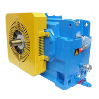
FLENDER H KM Series
Siemens FLENDER H KM Series Manuals
Manuals and User Guides for Siemens FLENDER H KM Series. We have
1
Siemens FLENDER H KM Series manual available for free PDF download: Assembly And Operating Instructions Manual
Siemens FLENDER H KM Series Assembly And Operating Instructions Manual (96 pages)
Gear unit
Brand:
Siemens
| Category:
Industrial Equipment
| Size: 0.93 MB
Table of Contents
Table of Contents
5
1 Technical Data
8
General Technical Data
8
Marking of the Gear Unit Designed in Accordance with Directive 94/9/EC
9
Ambient Temperature
9
Configurations and Weights
10
Gearunit Types
10
Weights
11
Measuringsurface Soundpressure Level
13
Measuringsurface Soundpressure Level for Bevelhelical Gear Units (B
13
Measuringsurface Soundpressure Level for Bevelhelical Gear Units (B
14
Measuringsurface Soundpressure Level for Helicalgear Units (H
15
Measuringsurface Soundpressure Level for Helicalgear Units (H
16
2 General Notes
17
Introduction
17
Copyright
17
3 Safety Instructions
18
Obligations of the User
18
Environmental Protection
19
Special Dangers and Personal Protective Equipment
20
4 Transport and Storage
21
Scope of Supply
21
Transport
21
Storing the Gear Unit
23
Standard Coating and Preservation
24
Interior Preservation with Preservative Agent
25
Exterior Preservation
25
5 Technical Description
26
General Description
26
Output Designs
27
Housing
27
Toothed Components
30
Lubrication
30
Splash Lubrication
30
Shaft Bearings
30
Shaft Seals
30
Radial Shaftsealing Rings
30
Taconite Seal
31
Backstop
32
Torquelimiting Backstop (Special Design)
33
Cooling
34
Fan
34
Cooling Coil
35
Addon Oilsupply System with Air Oilcooler
36
Addon Oilsupply Unit with Water Oilcooler
38
Pump
39
Water Oilcooler
39
Filter
39
Oiltemperature Monitoring
40
Oillevel Monitoring System
40
Bearingmonitoring System
41
Auxiliary Drive
41
Auxiliary Drive, Designed as a Maintenance Drive or Load Drive
42
Overrunning Clutch
44
Gear Unit with Auxiliary Drive and Torquelimiting Backstop
44
6 Fitting
45
General Information on Fitting
45
Unpacking
46
Installation of Gear Unit on Housing Base
46
Foundation
46
Description of Installation Work
46
Alignment
47
Mounting on a Foundation Frame
48
Mounting on a Concrete Foundation by Means of Stone Bolts or Foundation Blocks
49
Mounting on a Concrete Foundation by Means of Anchor Bolts
50
Assembly of a Shaftmounting Gear Unit with Hollow Shaft and Parallel Keyway
51
Preparatory Work
51
Fitting
52
Axial Fastening
52
Demounting
53
Shaftmounting Gear Unit with Hollow Shaft and Internal Spline to DIN 5480
55
Preparatory Work
55
Fitting
55
Fitting with Integrated du Bush
56
Fitting with Loose du Bush
56
Axial Fastening
56
Demounting
57
Shaftmounting Gear Unit with Hollow Shaft and Shrink Disk
58
Fitting
58
Fitting with Integrated du Bush
59
Fitting with Loose du Bush
59
Axial Fastening
59
Shrink Disk
60
Fitting the Shrink Disk
60
Demounting the Shrink Disk
62
Cleaning and Greasing the Shrink Disk
62
Remounting the Shrink Disk
63
Inspection of the Shrink Disk
63
Couplings, Clutches
64
Gear Unit with Flanged Shaft
65
Gear Unit with Block Flange
66
Mounting the Torque Arm for the Gearunit Housing
67
Attaching the Torque Arm
67
Mounting Supports for Gearunit Swing Base
68
Attaching the Support
68
Gear Units with Cooling Coil
69
Gear Unit with Addon Components
69
Gear Units with Addon Air Oilcooler
69
Gear Units with Addon Water Oilcooler
69
Gear Unit with Oiltemperature Monitoring System
69
Gear Unit with Oillevel Monitoring
69
Bearingmonitoring System
69
Gear Unit with Speed Transmitter
69
Final Work
70
Screwconnection Classes, Tightening Torques and Initial-Tensioning Forces
70
Screwconnection Classes
70
Tightening Torques and Initial-Tensioning Forces
71
7 Startup
73
Procedure before Startup
73
Removal of Preservative Agent
73
Filling with Lubricant
75
Oil Quantities
76
Startup
77
Oil Level
77
Gear Unit with Cooling Coil or External Oilsupply System
77
Gear Unit with Backstop
77
Gear Unit with Auxiliary Drive
78
Temperature Measurement
78
Bearing Monitoring (Vibration Measurement)
78
Checking Procedure
79
Removal from Service
79
Interior Preservation During Longer Disuse
79
Interior Preservation with Gear Oil
79
Interior Preservation with Preservative Agent
79
Interiorpreservation Procedure
80
Exterior Preservation
80
Exteriorpreservation Procedure
80
8 Operation
81
General
81
9 Faults, Causes and Remedy
82
General Information on Faults and Malfunctions
82
Possible Faults
82
10 Maintenance and Repair
86
General Notes on Maintenance
86
General Oilservice Lives
88
Description of Maintenance and Repair Work
88
Examine Water Content of Oil / Conducting Oil Analyses
88
Change Oil
88
Clean the Air Filter
88
Clean Fan and Gear Unit
89
Check Cooling Coil
89
Refill Taconite Seals with Grease
90
Check Air Oilcooler
90
Check Water Oilcooler
90
Check Hose Lines
91
Top up Oil
91
Checking Friction Linings of Torquelimiting Backstop
91
Checking Auxiliary Drive
91
Check Tightness of Fastening Bolts
91
Final Work
92
General Inspection of the Gear Unit
92
Lubricants
92
11 Spare Parts, Customerservice Addresses
93
Stocking Spare Parts
93
Spare Parts and Customerservice Addresses
93
12 Declarations
94
Declaration of Incorporation
94
Declaration of Conformity
94
Advertisement
Advertisement
Related Products
Siemens FLENDER H SH Series
Siemens FLENDER H VH Series
Siemens FLENDER H HH Series
Siemens FLENDER H DH Series
Siemens FLENDER H KH Series
Siemens FLENDER H FH Series
Siemens FLENDER H HM Series
Siemens FLENDER H DM Series
Siemens FLENDER H FM Series
Siemens FLENDER H PH Series
Siemens Categories
Industrial Equipment
Controller
Control Unit
Oven
Washer
More Siemens Manuals
Login
Sign In
OR
Sign in with Facebook
Sign in with Google
Upload manual
Upload from disk
Upload from URL