Sign In
Upload
Manuals
Brands
Siemens Manuals
Medical Equipment
Magnetom Viato Mobile
Siemens Magnetom Viato Mobile Manuals
Manuals and User Guides for Siemens Magnetom Viato Mobile. We have
1
Siemens Magnetom Viato Mobile manual available for free PDF download: Operator's And Service Manual
Siemens Magnetom Viato Mobile Operator's And Service Manual (140 pages)
1.5T Mobile MRI Systems By Marmon a Berkshire Hathaway Company
Brand:
Siemens
| Category:
Medical Equipment
| Size: 12.23 MB
Table of Contents
List of Revisions & Warnings
3
Revisions
3
Warnings & Safety Alert Conventions
4
Table of Contents
5
List of Figures
10
Section 1: Introduction
12
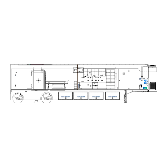
Figure 1: the Siemens Viato Mobile MRI System
12
Section 2: Safety Guidelines
14
Operator's General Safety Precautions
15
Magnet Safety
15
Chemical Safety
16
Electrical Safety
16
Transportation Safety
17
Section 3: Mobile Unit Overview
18
Air Ride Control Valves
18
Figure 2: Air Ride Control Valves
18
Canopy (Optional)
19
Figure 3: Canopy
19
Control Room Overall
20
Figure 4: Control Room Overall
20
Figure 5: Advanced Mobility System ID Tag & Job Number
20
Cryogen Compressor
21
Figure 6: Cryogen Compressor Cabinet
21
Exterior Overall
22
Figure 7: Exterior Overall
22
Equipment Room Overall
23
Figure 8: Equipment Room Overall
23
Exterior Staff Entry Door
24
Figure 9: Exterior Staff Door
24
Fuel Compartment
25
The Automatic Transfer Switch
25
Figure 10: Fuel Compartment
25
Figure 11: Power Supply Control Panel
25
Glad-Hand Connections
26
Figure 12: Glad Hand Connections
26
Hubbell All Weather Phone Cables
27
Figure 13: Hubbell All Weather Phone Cables
27
Levels
28
Figure 14: Levels
28
Magnet Room
29
Figure 15: Magnet Room Helium Rear Door
29
Mobile Unit Controls
31
Figure 16: Mobile Unit Controls
31
Phone & Data Line Connections
33
Figure 17: Phone & Data Line Connections
33
Scan Room Overall
34
Figure 18: Scan Room Overall
34
Stabilizing Stands
35
Figure 19: Stabilizing Stands
35
Stair Assembly
36
Figure 20: Stair Assembly (Standard)
36
Water / Wastewater Connections (Sink Option)
37
Figure 21: Fresh Water and Wastewater Connections
37
Section 4: Safety Systems
38
Door Interlock System
38
Figure 22: Interlocks
38
Service Door Equipment Room
39
Figure 23: Service Door
39
Emergency Lighting
40
Fire Suppression (Manual)
40
Figure 24: Emergency Lighting
40
Figure 25: Fire Extinguisher
40
Fire Detection System (Optional)
41
Figure 26: Smoke Detector
41
Figure 27: Fire Alarm Control Panel
41
Pull Station
42
Power Backup System
42
Figure 28: Fire Alarm Pull Station
42
NOVEC-1230 Fire Suppression System (Optional)
43
Figure 29: Fire Suppression Components
43
Control Unit Description
44
Enclosure with Door
44
Enclosure Door Options
44
Power Supply Unit
44
Printed Circuit Board
45
Figure 30: Printed Circuit Board (PCB)
45
Operator Interface
46
LED Indicators
46
Control Switches
47
Digital Display
47
Buzzer
47
Initiating Device Circuits (System Inputs)
47
Detection Inputs
47
Manual Release
48
Abort Switch
48
Figure 31: Abort Switch
48
Maintenance Switch
49
Supervisory Inputs
49
System Outputs
49
Figure 32: Maintenance Switch
49
Notification Appliance Circuits (Nacs)
50
Agent Release Circuits (ARC)
50
Trouble Relay
50
System Operation
51
Pull Station
51
Input / Output Matrix
52
Gauss Lines
53
Hydraulic Platform Lift
53
Magnet Field Warning Indicator
53
Marker Lights
53
Roll Door
54
Figure 33: Roll Door Emergency Release
54
System Shutdowns
55
Figure 34: Emergency Shutdown Buttons
55
Fire Detection System
56
Fire Suppression System (Optional)
56
Guarded Magnet Quench Button (Emergency Rundown Unit)
57
Manual Shutdown (Emergency Stop / A1 Stop)
57
Warning Lights
57
Power on Light
57
Transport Warning Light
57
Medical Transport Warning Light
57
Section 5: Mobile Unit Setup Procedure
58
Park the Mobile Unit
58
Lower the Landing / Stabilizing Legs
58
Disconnect the Tractor
58
Install the Rear Stabilizing Stands
59
Re-Level the Mobile Unit
59
Disconnect the Tractor Air and Electrical Lines
59
Lower the Auxiliary Support Legs
59
Install the Stair Assembly
60
Standard Stair Assembly
60
Stair Assembly with the Platform (Optional)
60
Connect to Shore Power
61
Automatic Transfer Switch (ATS) Panel (Underbody)
62
Connect the Phone and Data Lines
62
Connect the Water / Waste Hoses
62
Humidifier Water Fill
62
Fresh Water Supply Requirements (Sink Option)
63
Waste Water Connections (Sink Option)
63
Remove Restraining Hardware
63
Prepare the Medical System Per OEM Instructions
64
Canopy Deployment (if Applicable)
64
Section 6: Mobile Unit Transport Procedure
66
Canopy Retraction (if Applicable)
66
Return the Hydraulic Platform Lift to the Transport Position
66
Secure All Equipment
67
Automatic Transfer Switch (ATS) Panel (Underbody)
68
Remove and Store the Stair Assembly
69
Standard Stair System
69
Stair Assembly with the Platform (Optional)
69
Remove the Shore Power Connection
70
Disconnect the Water / Waste Hoses
70
Disconnect Phone and Data Lines
70
Raise the Auxiliary Support Legs
71
Connect the Tractor Air and Electrical Lines
71
Remove the Rear Stabilizing Stands
71
Connect the Tractor to the Mobile Unit
72
Raise the Landing / Stabilizing Legs
72
Verify that the Mobile Unit Is Ready for Transport
73
Section 7: Electrical System
74
120/208V AC Electrical Panel
75
Figure 35: 120/208V AC Electrical Panel
75
AC Electrical Panel
76
A1 Electrical Panel
76
Figure 36: 480V AC Electrical Panel
76
Figure 37: A1 Electrical Panel
76
Facility Power Connection
77
Figure 38: Shore Power Connection
77
Power Cable
78
Figure 39: Power Cable
78
Special Grounding Note
79
Figure 40: Power Supply Control Panel Ground Connection
79
Section 8: Generator
80
Figure 41: Generator
81
Automatic Transfer Switch (ATS) Panel (Underbody)
82
AC FAULT Indicator Light
82
Section 9: HVAC System
84
Figure 42: A/C Unit
84
Air Conditioning & Chiller
85
Figure 43: A/C / Chiller Control Panel
85
System Specifications and Descriptions
86
Exterior HVAC Specifications
86
Figure 44: HVAC Monitor and Alarm Panel
86
HVAC Humidifier System
87
Figure 45: Humidifier Water Tank
87
System Operation
88
Water Supply
88
Humidity Settings
89
Electrical Connections
89
Instructions
89
Figure 46: Humidifier External Water Connection
89
Interior HVAC Specifications
90
Figure 47: HVAC Components
90
Underbody Compartment Heater
91
Figure 48: Heater
91
Section 10: Hydraulic Platform Lift
92
Figure 49: Platform Lift Progression
92
Safety Features
93
Lift Controls
93
Figure 50: Platform Storage & Safety Latches
93
Handrails
94
Lift up Indicator Light
94
Remote Control Pendent
94
Figure 51: Remote Control Pendent
94
Transport Warning Light
95
Hydraulic System
95
Operation
95
Platform Lift Operation
96
Deploying the Platform Lift for Use with the Mobile Unit
96
Storing the Platform Lift for Transport of the Mobile Unit
96
Section 12: Landing / Stabilizing Legs
98
Figure 52: Landing / Stabilizing Leg Assembly
98
Stabilizing Stands
99
Rear Air Suspension System Controls
99
Figure 53: Air Bag Controls
99
Section 13: Lighting System
100
Emergency Lighting
100
Figure 54: Emergency Dual Beam Lighting
100
Exterior Lighting
101
Underbody Compartment Lighting
101
Service Lighting Optional
101
Figure 55: Compartment Light
101
Figure 56: Drop Light
101
Staff Door Lighting
102
Figure 57: Staff Door Lighting
102
Scene Lighting
103
Marker & Running Lights
104
Interior Lighting
104
Equipment Room
104
Figure 58: Equipment Room Lighting
104
Control Room
105
Scan Room
105
Magnet Room
105
Figure 59: Control Room Lighting
105
Figure 60: Scan Room Lighting
105
Figure 61: Scan Room / Magnet Room Lighting and Switches
106
Warning Lights
107
Power Warning Light
107
Transport Warning Light
107
Figure 62: Warning Lights
107
Medical Transport Warning Light
108
Figure 63: Lift Transport Warning
108
Section 14: General Maintenance
110
Daily Maintenance
110
Weekly Maintenance
111
Monthly Maintenance
111
Quarterly Maintenance
112
Section 15: Specific Maintenance
114
Door Closer Adjustments
114
Electrical System
115
Cryogen Compressor
115
Generator
115
Humidity System
115
HVAC System
116
Hydraulic Platform Lift
116
RF Shielding
117
Figure 64: RF Shielding
117
Section 16: Optional Accessories
118
Cold Weather Package (Optional)
118
Figure 65: Cold Weather Option
118
Appendix A: Mobile Unit Checklist
119
Mobile Unit Setup Checklist
120
Mobile Unit Transport Checklist
121
Appendix B: Troubleshooting
123
Hydraulic Platform Lift Is Inoperable
123
AC Power Indicator Light Is off
123
Transport Warning Light Is on
123
Suspension Transport Indicator Light Is Illuminated
124
Humidity Is out of Specifications
124
Temperature Is out of Specifications
126
Appendix C: HVAC Set Points
127
Appendix D: A-1 Circuit Malfunction Checklist
129
Category 1
129
Category 2
129
Appendix E: Lockout/Tagout Procedures
131
Specific Energy Control Procedures
131
Specialty Vehicle Trailer: Siemens Aera MRI System
131
Appendix F: Coil Storage
133
Figure 66: Coil Storage
133
Appendix G: Quarterly Maintenance Checklist
135
Advertisement
Advertisement
Related Products
Siemens MAGNETOM Skyra
Siemens MAGNETOM Skyra fit
Siemens MAGNETOM Aera
Siemens MammoReport Plus
Siemens MAMMOMAT 3000
Siemens MAMMOMAT Novation DR
Siemens MAMMOMAT 1000
Siemens MAMMOMAT Inspiration
Siemens MAMMOMAT Nova Opdima 3000
Siemens MAMMOMAT Nova Opdima 1000
Siemens Categories
Industrial Equipment
Controller
Control Unit
Oven
Washer
More Siemens Manuals
Login
Sign In
OR
Sign in with Facebook
Sign in with Google
Upload manual
Upload from disk
Upload from URL