Sign In
Upload
Manuals
Brands
Siemens Manuals
Computer Hardware
Metro 21 M216KA
Siemens Metro 21 M216KA Manuals
Manuals and User Guides for Siemens Metro 21 M216KA. We have
1
Siemens Metro 21 M216KA manual available for free PDF download: Operator's Manual
Siemens Metro 21 M216KA Operator's Manual (414 pages)
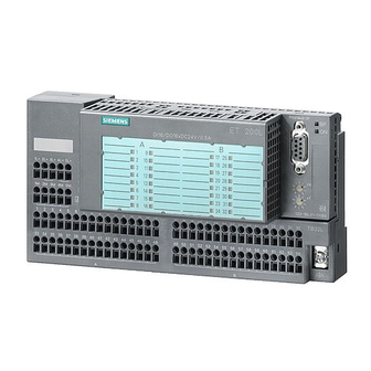
Distributed I/O Device
Brand:
Siemens
| Category:
Computer Hardware
| Size: 4.84 MB
Table of Contents
Edition
2
Table of Contents
7
1 Product Overview
19
What Is the et 200 Distributed I/O System
20
A Typical PROFIBUS-DP Installation
20
What Is the et 200L Distributed I/O Device and Smart Connect
21
Wiring
21
General Components for the et 200L, et 200L-SC, et 200L-SC IM-SC
24
What Is the et 200L Block I/O Device
26
View of the et 200L Distributed I/O Device
26
Components of the et 200L Distributed I/O Device
27
Commissioning
27
What Is the et 200L-SC Modular I/O Device
28
Components of a et 200L-SC
29
What Is the et 200L-SC IM-SC Fine-Step Modular I/O Device
31
Et 200L-Sc IM-Sc
31
Components of an et 200L-SC IM-SC
32
2 Installation
35
Installing the et 200L TB 16L/TB 32L Terminal Block and Supplementary Terminal
37
Installing the Terminal Block
38
Disassembling the Terminal Block
39
Installing and Disassembling the et 200L Electronics Block
40
Installing the Electronics Block
40
Installing the TB 16IM-SC/TB 16SC Terminal Block
41
Snapping the Terminal Block Onto the Rail
42
Sliding the Labeling Strip into the Terminal Block
43
Positioning the Coding Slide Switches
45
Using the Screwdriver
45
Designation Plate with Labeling Strips (Reduced in Size)
46
Connecting Smart Connect Electronic Modules to the TB 16IM-SC/TB 16SC Terminal Block
47
Et 200L-Sc IM-Sc
48
Installing the et 200L IM-SC Interface Module on the TB 16IM-SC Terminal Block
51
Installing the IM-SC Interface Module
51
Setting the et 200L PROFIBUS Address
52
Installing a Supplementary Terminal and Shield Terminal on the TB 16IM-SC/TB 16SC Terminal Block
53
Securing a Supplementary Terminal to the Terminal Block
53
Connecting a Shield Terminal to the Supplementary Terminal
54
3 Wiring
57
General Rules and Regulations
59
Configuring the Electrical Installation
61
DIN VDE Regulations for Installation of a Controller
61
Operating the et 200L from a Grounded Supply
63
Power Supply of the Terminal Block
64
Wiring Rules
65
Pinout of the PROFIBUS-DP Terminal Connection
65
How the Spring Terminal Works
66
Wiring the et 200L TB 16L/TB 32L Terminal Block
67
Terminal Connections on Terminal Block TB 16L
67
Alternative Ways of Connecting the Voltage Supply
68
Pinout of the PROFIBUS-DP Terminal Connection
69
Wiring the Smart Connect TB 16SC Terminal Block
70
Front View of the Terminal Block
70
Wiring the et 200L TB 16IM-SC Terminal Block
72
Connections of the TB 16IM-SC Terminal Block
72
Connection Alternatives for the Power Supply
73
Wiring the et 200L IM-SC Interface Module
74
Connections of the IM-SC Interface Module
74
Assignment of the PROFIBUS-DP Connection at the IM-SC Interface Module
75
Length of Insulation Stripped
76
Wiring the PROFIBUS-DP Screw-Type Terminal
76
Connecting the Power Supply
77
Functioning of the Bus Terminating Switch
77
Using the Supplementary Terminal for the TB 16SC/TB 16IM-SC
78
Connecting Shielded Lines to the Shield Terminal of the Supplementary Terminals
79
Connecting the Smart Connect SC to the et 200L-SC/TB 16IM-SC
80
4 Commissioning
81
Configuration Software
82
Commissioning the et 200L and Smart Connect
83
Replacing SC Electronic Modules
85
5 Diagnostics
87
Diagnostics Using the Leds
88
Diagnostics Using the LED Display
88
Diagnostics Using the Leds of the et 200L-SC for et 200L-SC IM-SC
90
Slave Diagnostics
91
General Remarks on Diagnostics
92
Structure of the Slave Diagnosis
93
Structure of Station Statuses 1 to 3, Master Station Number and Manufacturer Identification
94
Structure of Station Status 1 (Byte 0)
94
Structure of Station Status 2 (Byte 1)
95
Structure of the Module Diagnosis for the et 200L-SC and et 200L-SC IM-SC
96
Structure of the Module Diagnosis with the COM/S7 Configuration Software for the et 200L-SC
96
Structure of the Module Diagnosis with the COM/S7 Configuration Software for the et 200L-SC IM-SC
97
Structure of the Module Diagnosis with any Configuration Software for the et 200L-SC, et 200L-SC IM-SC
98
Structure of the Station Diagnosis for the et 200L-SC and et 200L-SC IM-SC
99
Structure of Station Diagnosis
99
Bytes 13 to 16 for the Diagnostic Interrupt
100
Structure of Slave Diagnosis for Default Start-Up of et 200L-SC and et 200L-SC IM-SC
101
Slave Diagnosis for Default Start-Up of the et 200L-SC and et 200L-SC IM-SC
101
Standards and Certification
104
Electromagnetic Compatibility
106
Shipping and Storage Conditions
108
Mechanical and Climatic Environmental Conditions
109
Details of Insulation Testing, Safety Class, and Degree of Protection
110
Rated Voltage of the et 200L Distributed I/O Device
111
7 Terminal Blocks and Supplementary T Erminals - T Echnical Data
114
Terminal Block TB 16L
114
6 Es7 193-1Ch00-0Xa0, 6Es7 193-1Ch10-0Xa0
114
ET 200L Electronics Blocks Technical Data
114
The TB 16L Terminal Block with the Electronics Block Clipped On, Dimension Drawing
114
Pinout of the TB 16L Terminal Block
115
6Es7 193-1Cl00-0Xa0, 6Es7 193-1Cl10-0Xa0
116
Terminal Block TB 32L
116
Drawing
117
The TB 32L Terminal Block with the Electronics Block Clipped On, Dimension Drawing
117
Pinout of the TB 32L Terminal Block
118
Terminal Block TB 16L AC 6ES7 193-1CH20-0XA0
119
The TB 16L AC Terminal Block with the Electronics Block Mounted, Dimension
120
Drawing (MM)
120
Pinout of the TB 16L AC Terminal Block
121
Terminal Block TB 16SC
122
Front Elevation of the Terminal Block
124
Block Diagram of the TB16 SC Terminal Block
125
Terminal Block TB 16IM-SC
126
The TB 1616IM-SC Terminal Block with the 16IM-SC Interface Module Mounted, Dimension Drawing
128
Supplementary Terminals for the TB 16L and TB 32L
130
Supplied Versions of the Supplementary Terminals
130
TB 16L/TB 32L Supplementary Terminals, Dimension Drawing
131
Supplementary Terminals for the TB 16SC and TB 16IM-SC
132
Supplied Versions of the Supplementary Terminals TB16SC/ TB 16IM-SC
132
TB 16SC/TB 16IM-SC Supplementary Terminals, Dimension Drawing
132
Assignment of the et 200L Electronic Blocks to the Terminal Blocks
133
Electronics Block L 16 DI DC 24 V - 6ES7 131-1BH00-0XB0
135
View of the L 16 DI DC 24 V Electronics Block
135
Block Diagram of the L 16 DI DC 24 V Electronics Block
136
Electronics Block L 16 DO DC 24 V/0.5 a - 6ES7 132-1BH00-0XB0
138
View of the L 16 DO DC 24 V/0.5 a Electronics Block
138
Block Diagram of the L 16 DO DC 24 V/0.5 a Electronics Block
139
Electronics Block L 32 DI DC 24 V 6ES7 131-1BL00-0XB0
141
View of the L 32 DI DC 24 V Electronics Block
141
Block Diagram of the L 32 DI DC 24 V Electronics Block
142
Electronics Block L 32 DO DC 24 V/0.5 a -6ES7 132-1BL00-0XB0
144
View of the L 32 DO Electronics Block DC 24 V/0.5 a
144
Block Diagram of the L 32 DO DC 24 V/0.5 a Electronics Block
145
Electronics Block L 16 DI/16 DO DC 24 V/0.5 a – 6ES7 133-1BL00-0XB0
147
View of the L 16 DI/16 DO DC 24 V/0.5 a Electronics Block
147
Block Diagram of the L 16 DI/16 DO DC 24 V/0.5 a Electronics Block
148
Electronics Block L 16 DI AC 120 V – 6ES7 131-1EH00-0XB0
150
View of the L 16 DI AC 120 V Electronics Block
150
Block Diagram of the L 16 DI AC 120 V Electronic Block
151
Electronics Block L 16 DO AC 120 V/1.0 a – 6ES7 132-1EH00-0XB0
153
View of the L 16 DO AC 120 V/1.0 a Electronics Block
153
Block Diagram of the L 16 DO AC 120 V/1.0 a Electronics Block
154
Electronics Block L 16 RO DC 24 V/AC 120 V/2.0 a 6ES7 132-1JH00-0XB0
156
View of the L 16 RO DC 24 V/AC 120V/2.0 a Electronics Block
156
Block Diagram of the L 16 RO DC 24 V/AC 120 V/2.0 a Electronics Block
157
8 ET 200L Electronics Blocks - T Echnical Data
135
Service Life of the Contacts
159
Electronics Block L 8 DI/8 DO AC 120 V/1.0 a – 6ES7 133-1EH00-0XB0
160
View of the L 8 DI/8 DO AC 120 V/1.0 a Electronics Block
160
Block Diagram of the L 8 DI/8 DO AC 120 V/1.0 a Electronics Block
161
Electronics Block L 8 DI AC 120 V/8 RO DC 24 V/AC 120 V/2.0 a 6ES7 133-1JH00-0XB0
163
View of the L 8DI AC 120 V/8 RO DC 24 V/AC 2.0A Electronics Block
163
Block Diagram of the L 8 DI AC 120 V/8 RO DC 24 V/AC 120 V/2.0A Electron Ics Block
164
Service Life of the Contacts
166
Assignment of the Interface Module/Et 200L-SC Electronics Blocks to the Terminal Blocks
167
Interface Module IM-SC
168
IM-SC Interface Module
168
Block Diagram of the IM-SC Interface Module
169
Electronics Block L-SC 16 DI DC 24 V – 6ES7 131-1BH11-0XB0
170
View of the L-SC 16 DI DC 24 V Electronics Block
170
Block Diagram of the L-SC 16 DI DC 24 V Electronics Block
171
Electronics Block L-SC 16 DO DC 24 V/0.5 a – 6ES7 132-1BH11-0XB0
173
View of the L-SC 16 DO DC 24 V/0.5 a Electronics Block
173
Block Diagram of the L-SC 16 DO DC 24 V/0.5 a Electronics Block
174
Electronics Block L-SC 32 DI DC 24 V – 6ES7 131-1BL11-0XB0
176
View of the L-SC 32 DI DC 24 V Electronics Block
176
Block Diagram of the L-SC 32 DI DC 24 V Electronics Block
177
Electronics Block L-SC 16 DI/16 DO DC 24 V/0.5 a 6ES7 133-1BL10-0XB0
179
View of the L-SC 16 DI/16 DO DC 24 V/0.5 a Electronics Block
179
Block Diagram of the L-SC 16 DI/16 DO DC 24 V/0.5 a Electronics Block
180
9 ET 200L-SC Electronics Blocks – Technical Data
167
10 SC Digital Electronic Modules – Technical Data
183
Digital Electronic Module 2DIDC24V
184
Front and Side Elevations of the 2DIDC24V Digital Electronic Module
184
Block Diagram of the 2DIDC24V Digital Electronic Module
185
Digital Electronic Module 2DODC24V0.5A
187
Front and Side Elevations of the 2DODC24V0.5A Digital Electronic Module
187
Block Diagram of the 2DODC24V0.5A Digital Electronic Module
188
Digital Electronic Module 2DODC24V2A
190
Front and Side Elevations of the 2DODC24V2A Digital Electronic Module
190
Block Diagram of the 2DODC24V2A Digital Electronic Module
191
Digital Electronic Module 1DIAC120/230V
193
Front and Side Elevations of the 1DIAC120/230V Digital Electronic Module
193
Block Diagram of the 1DIAC120/230V Digital Electronic Module
194
Digital Electronic Module 1DOAC120/230V1A
196
Front and Side Elevations of the 1DOAC120/230V1A Digital Electronic Module
196
Block Diagram of the 1DOAC120/230V1A Digital Electronic Module
197
Digital Electronic Module 1Dorel.ac230V, DC 24 V to 120 V
199
Front and Side Elevations of the 1Dorel.ac230V Digital Electronic Module
199
Block Diagram of the 1Dorel.ac230V Digital Electronic Module
200
Switching Capacity and Lifetime of the Contacts
202
Analog Value Representation for Analog Input Modules in S7 Number
203
Analog Value Representation in S7 Number Format
203
Behavior of the Analog Output Modules
203
Connecting Loads/Actuators to Analog Outputs
203
Conversion, Cycle, Settling and Response Times of the Analog
203
Output Modules
203
Default Parameters of the Analog Output Modules
203
SC Analog Electronic Modules – Parameters
203
Parameters of the Analog Input Modules
204
Notes on the Parameters of the Analog Input Modules
206
Format
207
Wiring Unused Analog Output Modules
203
11 Scanalog Electronic Modules - Parameters
206
Default Parameters of the Analog Input Modules
208
Behavior of the Analog Input Modules
209
Effect of the Operating Mode of the CPU and the Supply Voltage L+ Compensation the Analog Input Values
209
Conversion and Cycle Times of the Analog Input Channels
210
Connecting Thermocouples
211
Structure of Thermocouples
211
Surement Module, to Slot a of the Terminal Block (Example TB 16SC)
215
Connecting Non-Isolated Voltage Sensors
216
Connecting Voltage Sensors (Example TB 16SC)
216
Connecting Current Sensors
217
Connecting 4-Wire Measuring Transducers (Example TB 16SC)
217
Connecting 2-Wire Measuring Transducers (Example TB 16SC)
218
Connecting Resistance Thermometers and Resistors
219
Conductor Connection for Resistance Thermometers and Resistors (Exam Ple TB 16SC)
219
Floating Measuring Sensors
220
Wiring Unused Inputs of Analog Input Modules
221
11.12 Parameters of the Analog Output Modules
222
Notes on the Parameters of the Analog Output Modules
223
Output Types/Output Ranges of the Analog Output Modules
223
Default Parameters of the Analog Output Modules
224
Effect of the Operating Mode of the CPU and the Supply Voltage L+ on the Analog Output Values
225
Conversion, Cycle, Settling and Response Times of the Analog Output Modules
226
Response Time of the Analog Output Channels
227
Connecting Loads/Actuators to a Current Output (Example TB 16SC)
228
Connecting Loads/Actuators to a Voltage Output Via a 4-Wire Circuit (Example TB 16SC)
229
Analog Measurement Ranges for Input Channels in S7 Number Format
232
Unipolar Input Ranges
232
Life-Zero Input Ranges
233
Analog Value Representation for Analog Input Modules in S7 Number Format
234
11.22 Analog Output Ranges for Output Channels in S7 Number Format
239
Bipolar Output Ranges
239
Unipolar Output Ranges
239
Life-Zero Output Ranges
240
Analog Value Representation for Output Modules in S7 Number Format
241
11.24 Analog Value Representation in S5 Number Format
243
Representation of the Measurement Ranges for Analog Inputs
243
Representation of the Measurement Rangesfor Analog Outputs
244
Analog Measurement Ranges for Input Channels in S5 Number Format
245
Bipolar Input Ranges
245
Unipolar Input Ranges
245
Life-Zero Input Ranges
246
Analog Value Representation for Analog Input Modules in S5 Number Format
247
Analog Output Ranges for Output Channels in S5 Number Format
252
Bipolar Output Ranges
252
Unipolar Output Ranges
252
Life-Zero Output Ranges
253
Analog Value Representation for Output Modules in S5 Number Format
254
12 SC Analog Electronic Modules - Technical Data
258
12.1 Analog Electronic Module 2 AI U
258
Front and Side Elevations of the 2 AI U Analog Electronic Module
258
Block Diagram of the 2 AI U Analog Electronic Module
259
Static Parameters of the 2 AI U Electronic Module
260
Jump Response
261
12.2 High-Speed Analog Electronic Module 2 AI HS U
264
Front and Side Elevations of the 2 AI HS U High Speed Analog Electronic Module
264
Block Diagram of the 2 AI HS U High-Speed Analog Electronic Module
265
Static Parameters of the 2 AI HS U Highspeed Electronic Module
266
Jump Response
267
Analog Electronic Module 2 AI I
270
Front and Side Elevations of the 2 AI I Analog Electronic Module
270
Block Diagram of the 2 AI I Analog Electronic Module
271
Static Parameters of the 2 AI I Electronic Module
272
Jump Response
273
Analog Electronic Module 2 AI I
276
Front and Side Elevations of the 2 AI I Analog Electronic Module
276
Block Diagram of the 2 AI I Analog Electronic Module
277
Static Parameters of the 2 AI I Electronic Module
278
Jump Response
279
Front and Side Elevations of the 2 AI HS I High-Speed Analog Electronic Mod Ule (0/4–20Ma, 4-Wire Measuring Transducer)
282
Static Parameters of the 2 AI HS I Electronic Module
284
High-Speed Analog Electronic Module 2 AI HS I
282
High-Speed Analog Electronic Module 2 AI HS I (0/4-20 Ma, 4-Wire Measuring Transducer)
282
Jump Response
285
(4-20 Ma, 2-Wire Measuring Transducer)
288
Front and Side Elevations of the 2 AI HS I High-Speed Analog Electronic Mod Ule (4–20Ma, 2-Wire Measuring Transducer)
288
Block Diagram of the 2 AI HS I High-Speed Analog Electronic Module (4–20Ma 2-Wire Measuring Transducer)
289
Static Parameters of the 2 AI HS I Electronic Module (4–20Ma, 2-Wire Measur Ing Transducer)
290
Jump Response
291
12.7 Analog Electronic Module 2 AI TC
294
Front and Side Elevations of the 2 AI TC Analog Electronic Module
294
Block Diagram of the 2 AI TC Analog Electronic Module
295
Static Parameters of the 2 AI TC Electronic Module
296
Dynamic Parameters of the 2 AI TC Electronic Module
296
Jump Response
297
12.8 Analog Electronic Module 1 AI RTD
300
Front and Side Elevations of the 1 AI RTD Analog Electronic Module
300
Block Diagram of the 1 AI RTD Analog Electronic Module
301
Static Parameters of the 2 AI RTD Electronic Module
302
Jump Response
303
12.9 Analog Electronic Module 1 AO U
306
Front and Side Elevations of the 1 AO U Analog Electronic Module
306
Block Diagram of the 1 AO U Analog Electronic Module
307
Static Parameters of the 1 AO U Electronic Module
308
12.10 Analog Electronic Module 1 AO I
310
Front and Side Elevations of the 1 AO I Analog Electronic Module
310
Block Diagram of the 1 AO I Analog Electronic Module
311
Static Parameters of the 1 AO I Electronic Module
312
13 The 1Count40Khz Counter Module
316
13.1 Front and Side Elevations
316
Displays, Colour and Functions of the Leds
316
Front and Side Elevations of the 1Count40Khz Counter Module
316
13.2 Block Diagram
317
Block Diagram of the 1Count40Khz Counter Module
317
13.3 Functions of the Counter Module
318
Continuous Downward Counting
318
Continuous Upward Counting
318
Single-Pass Counting with Loaded Value and Gate Function
319
Periodic Upward Counting
320
Periodic Downward Counting
320
Single-Pass Downward Counting
319
Single-Pass Upward Counting
319
24V Pulse Initiator With/Without Direction Indicator
321
Signals of a 24V Pulse Initiator with Direction Indicator
321
Gate Functions
322
Opening and Closing of a Gate
322
Digital Output
323
Example 1: the Output Is Set to be Active from the Comparison Value to Overflow
326
Example 2: the Output Is Set to be Active from the Comparison Value to un Derflow
326
Example 3: the Output Is Set to be Active for the "Pulse Duration on Reaching the Comparison Value Counting Upward"
327
Example 4: the Output Is Set to be Active for the "Pulse Duration on Reaching the Comparison Value Counting Downward"
327
Example 5: the Output Is Set to be Active for the "Pulse Duration on Reaching the Comparison Value Counting Upward/Downward"
327
Wiring the Counter and Putting the Counter into Operation
328
Connecting a Pulse Initiator with a Direction Signal (Example TB 16SC)
329
Wiring the Counter
329
Putting the Counter into Operation
330
Parameter List
331
Parameters of the Counter Module
331
Subdivision of the Data Areas
333
Application Examples
335
Example 1
335
Example 1, Continued
336
Example 2
337
Example 2, Continued
338
Technical Data
339
A-1 Terminal Block Order Numbers
342
A-2 Electronics Block Order Numbers
342
A.1 Order Numbers for et 200L Components
342
A-3 Supplementary Terminal Order Numbers
343
A-1 Labeling Strips 6ES7 193-1BH00-0XA0
344
A-2 Labeling Strips 6ES7 193-1BL00-0XA0
345
A-4 Terminal Block and Terminal Order Numbers
346
A-5 Digital SC Electronic Module Order Numbers
346
A.2 Order Numbers for Smart Connect SC Components
346
A-6 Analog SC Electronic Module Order Numbers
347
A-7 Function Modules
347
A-3 Labeling Strips for Smart Connect
348
A-8 Accessories for the et 200 Distributed I/O Device
349
A.3 Order Numbers for PROFIBUS Accessories
349
A-10 Manuals for et 200 on SIMATIC S5
350
A-9 Manuals for STEP 7 and SIMATIC S7
350
B-1 Version der Projektier-Software
352
B-2 Data for PROFIBUS-DP
353
B-3 Maximum Number of Inputs and Outputs with the et 200L
354
B-4 Maximum Number of Inputs and Outputs with the et 200L-SC or et 200L-SC IM-SC
354
C-1 DP Identifiers for the et 200L
356
C.1 Identifiers for the et 200L
356
C-2 Types of et 200L-SC of et 200L-SC IM-SC Start-Up
357
C.2 Types of et 200L-SC or et 200L-SC IM-SC Start-Up
357
C-3 Structure of the Configuration Frame
358
C.3 Configuration Frame for the et 200L-SC
358
C-4 Identifiers for the et 200L-SC
360
C.3.1 Identifiers for the et 200L-SC
360
C-5 Identifiers for the Smart Connect with Digital et 200L-SC Modules
361
C-6 Identifiers for the Smart Connect with Analog et 200L-SC Modules
361
C-7 Identifiers for the Smart Connect with Digital et 200L-SC IM-SC Modules
363
C-8 Identifiers for the Smart Connect with et 200L-SC IM-SC Analog Modules
363
C.3.2 Identifiers for the et 200L-SC IM-SC
363
C.3.3 Configuration Frame Example
365
C-1 Structure of the Parameterization Frame of the et 200L-SC and et 200L-SC IM-SC
368
C.4 Parameterization Frame for the et 200L-SC or et 200L-SC IM-SC
368
C-2 Standard Section of the Parameterization Frame
370
C-3 Parameters for the Status
370
C.4.1 Standard Section and Parameters for the Status
370
C-9 Data Records for the et 200L-SC
371
C.4.2 Parameters for the Smart Connect Section
371
C-10 Data Records for the et 200L-SC IM-SC
372
C-4 Structure of Data Record 0
373
C.4.3 Data Record 0
373
C-5 Structure of the Header of Data Record 128
374
C.4.4 Data Record 128
374
C-6 Structure of Data Record 128, Bytes 7 to 62
375
C-7 Structure of the Header of Data Record 128
376
C.4.5 Data Record 130
376
C-8 Structure of Data Record 130 for Single-Channel Modules
377
C-9 Structure of Data Record 130 for Two-Channel Modules
377
C-10 Structure of Data Record 130 for the 1Count40Khz Counter Module
378
C-11 AI Parameters in Byte 11 and 16 of DS130
378
C-11 AI Parameters in Byte 12 or 17 of DS130
379
C-12 AO Parameters in Byte 11 or 16 of DS130
379
C-12 1Count40Khz Counter Module – Purpose of Bytes 11 to 17 of Data Record 130
380
C-13 et 200L-SC IM-SC Example
381
C.4.6 Parameterization Frame Example
381
C.5 Default Start-Up
385
C-14 Type Files for the et 200L-SC Default Start-Up with Digital SC Modules
386
C.5.1 Default Start-Up with Digital Smart Connect Modules
386
C-13 Structure of the Parameterization Frame
388
C-14 Default Setting for Digital SC Modules with the et 200L-SC
388
C-15 Default Setting for Digital SC Modules with the et 200L-SC IM-SC
389
C-15 et 200L-SC: Configuration Frame Extension for Analog Smart Connect Mod Ules
390
C-16 et 200L-SC IM-SC: Configuration Frame Extension for Analog Smart Connect Modules
390
C.5.2 Default Start-Up with Analog Smart Connect Modules
390
C-16 Structure of the Parameterization Frame
391
C-17 Default Setting for Analog Smart Connect Modules
392
D.1 What Is ESD?
396
D-1 Electrostatic Voltages Which Can Build up on a Person
397
D.2 Electrostatic Charging of Persons
397
D.3 General Protective Measures against Electrostatic Discharge Damage
398
Advertisement
Advertisement
Related Products
Siemens Metro 21 M216KASPC
Siemens Metro 21 M216KASP
Siemens Micromaster 21-0DC50
Siemens Micromaster 21-5DC50
Siemens 21-0TP50
Siemens 21-3TP50
Siemens 21-0TP70
Siemens 21-3TP70
Siemens 21-8TP70
Siemens ADVIA 2120i
Siemens Categories
Industrial Equipment
Controller
Control Unit
Oven
Washer
More Siemens Manuals
Login
Sign In
OR
Sign in with Facebook
Sign in with Google
Upload manual
Upload from disk
Upload from URL