Sign In
Upload
Manuals
Brands
Siemens Manuals
Industrial Equipment
NXAIR
Siemens NXAIR Manuals
Manuals and User Guides for Siemens NXAIR. We have
2
Siemens NXAIR manuals available for free PDF download: Operating Instructions Manual, Installation Instructions Manual
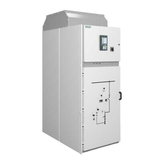
Siemens NXAIR Operating Instructions Manual (436 pages)
Air-Insulated Switchgear ≤ 17.5 kV / ≤ 40 kA / ≤ 4000 A Busbar Current
Brand:
Siemens
| Category:
Industrial Equipment
| Size: 21.75 MB
Table of Contents
1 Safety Instructions
3
Table of Contents
4
2 General Instructions
9
Five Safety Rules of Electrical Engineering
9
Hazardous Substances
9
Personal Protective Equipment (PPE)
10
Due Application
10
Qualified Personnel
10
Update of the Firmware of Protection Relays
11
3 Features
12
4 Technical Data
13
Complete Switchgear
13
Basic Prescriptions and Standards
13
Electromagnetic Compatibility - EMC
14
Rating Plates
14
IAC Classification
14
Panel Dimensions
15
Room Planning
17
Operating Conditions
17
Vacuum Circuit-Breaker Type 3AE
17
Operating Instructions for Circuit-Breaker Type 3AE
18
Contactor Type 3TL and 3TM
18
Operating Instructions for Contactor Type 3TL8 and 3TM3
19
Switch-Fuse Combination Type L-TRI 5F
20
Operating Instructions for Switch-Fuse Combination L-TRI 5F
20
5 Overview of Panel Types
21
6 Panel Design
25
Basic Design
25
Basic Design Circuit-Breaker Panel
26
Basic Design Circuit-Breaker Panel with Forced Ventilation
26
Basic Design Contactor Panel with Panel Width 435 MM
27
Basic Design Contactor Panel with Panel Width 600 MM
27
Basic Design Switch-Disconnector Panel
28
7 Interlocks
29
Mechanical Interlocks in Panel Versions with Withdrawable Parts
29
Mechanical Interlocks in Panel Versions with Switching-Device Trucks
30
Mechanical Interlocks in Panel Versions with Switch-Fuse Combination
30
Additional Electromagnetic Interlocks (Optional)
31
Additional Padlock Interlock (Optional)
31
Additional Key-Operated Interlock (Optional)
32
8 Accessories
33
Operating Tools
33
Service Truck
35
Service Truck Versions
35
9 Customer Support
38
Service
38
Repairs
38
Before You Call
38
Service Contact
38
10 Operating the Circuit-Breaker Panel
39
Control Elements at the Front Side of the Panel
39
Position Indicators Visible on High-Voltage Door
40
Access to Compartments
40
Opening the High-Voltage Door
41
Closing the High-Voltage Door
42
High-Voltage Door with Ventilation Flap
44
Positions of the Withdrawable Circuit-Breaker / Circuit-Breaker Truck
46
Racking the Withdrawable Circuit-Breaker / Circuit-Breaker Truck to Service Position
47
Racking the Withdrawable Circuit-Breaker / Circuit-Breaker Truck to Test Position
50
Closing the Circuit-Breaker Electrically
53
Opening the Circuit-Breaker Electrically
54
Closing the Circuit-Breaker Manually
55
Opening the Circuit-Breaker Manually
58
Discharging the Spring Energy Store
60
Charging the Spring Energy Store Manually
61
Earthing the Feeder Manually
64
Earthing the Feeder Manually
66
Removing the Low-Voltage Connector
69
Plugging on the Low-Voltage Connector
70
Taking the Withdrawable Circuit-Breaker out of the Panel
72
Inserting the Withdrawable Circuit-Breaker in a Panel
77
Taking the Circuit-Breaker Truck out of the Panel
86
Inserting the Circuit-Breaker Truck in a Panel
89
11 Operating the Disconnecting Panel
98
Control Elements at the Front Side of the Panel
98
Position Indicators Visible on High-Voltage Door
98
Access to Compartments
99
Opening or Closing the High-Voltage Door
99
Racking the Withdrawable Disconnector Link / Disconnector Truck
99
Removing or Plugging on the Low-Voltage Connector
101
Taking the Withdrawable Disconnector Link / Disconnector Truck out of a Panel or Inserting in a Panel
101
Earthing or De-Earthing the Feeder Manually
101
Design of the Withdrawable Disconnector Link / Disconnector Truck
101
12 Operating the Metering Panel
102
Control Elements at the Front Side of the Panel
102
Position Indicator Visible on High-Voltage Door
102
Access to Compartments
103
Opening or Closing the High-Voltage Door
103
Racking the Withdrawable Metering Part / Metering Truck
103
Removing or Plugging on the Low-Voltage Connector
103
Taking the Withdrawable Metering Part / Metering Truck out of the Panel or Inserting in a Panel
104
Replacing Protection Fuse-Links
104
13 Operating the Contactor Panel with Panel Width 435 MM
109
Control Elements at the Front Side of the Panel
109
Position Indicator Visible on High-Voltage Door
110
Access to Compartments
110
Opening the High-Voltage Door
110
Closing the High-Voltage Door
111
Positions of the Contactor Truck
113
Racking the Contactor Truck to Service Position
114
Racking the Contactor Truck to Test Position
116
Closing the Contactor Electrically
118
Opening the Contactor Electrically
118
Opening the Contactor Manually
119
Manual Emergency Opening of the Contactor
121
Operating Conditions Without Auxiliary Voltage
122
Earthing the Feeder Manually
125
Earthing the Feeder Manually
127
Taking the Contactor Truck out of the Panel
129
Inserting the Contactor Truck in a Panel
133
Replacing HV HRC Fuse-Links
138
Motor Starting Currents
146
Coordinating the Components of the Motor Circuit
146
14 Operating the Contactor Panel with Panel Width 600 MM
148
Control Elements at the Front Side of the Panel
148
Position Indicators Visible on High-Voltage Door
149
Access to Compartments
149
Opening the High-Voltage Door
150
Closing the High-Voltage Door
151
Positions of the Contactor Truck
153
Racking the Contactor Truck to Service Position
154
Racking the Contactor Truck to Test Position
157
Closing the Contactor Electrically
160
Opening the Contactor Electrically
161
Opening the Contactor Manually
162
Operating Conditions Without Auxiliary Voltage
164
Earthing the Feeder Manually
169
Earthing the Feeder Manually
171
Removing the Low-Voltage Connector
173
Plugging O the Low-Voltage Connector
175
Taking the Contactor Truck out of the Panel
177
Inserting the Contactor Truck in a Panel
180
Replacing HV HRC Fuse-Links
190
Motor Starting Currents
198
Coordinating the Components of the Motor Circuit
198
Replacing Protection Fuse-Links for the Control Transformer
199
15 Operating the Busbar Connection Panel Type I
203
Control Elements at the Front Side of the Panel
203
Position Indicator Visible on High-Voltage Door
203
Access to Compartments
204
Opening or Closing the High-Voltage Door
204
Racking the Withdrawable Metering Part / Metering Truck
204
Removing or Plugging on the Low-Voltage Connector
204
Taking the Withdrawable Metering Part / Metering Truck out of a Panel or Inserting in a Panel
205
Replacing Protection Fuse-Links
205
16 Operating the Busbar Connection Panel Type II
210
Panel Front
210
Opening the High-Voltage Door
210
Closing the High-Voltage Door
211
17 Operating the Busbar Current Metering Panel
213
Panel Front
213
Opening the High-Voltage Door
213
Closing the High-Voltage Door
214
18 Operating the Switch-Disconnector Panel
216
Control Elements at the Front Side of the Panel
216
Position Indicators Visible on High-Voltage Door
217
Access to Compartments
217
Opening the High-Voltage Door
217
Closing the High-Voltage Door
219
Operating the Switch-Fuse Combination to CLOSED Position
221
Operating the Switch-Disconnector to OPEN Position
224
Operating Lever for Earthing Switch
226
Earthing the Feeder Manually
227
Earthing the Feeder Manually
230
Replacing HV HRC Fuse-Links
233
19 Operating the Removable Voltage Transformers
239
Control Elements on the Door to the Voltage Transformer Compartment
239
Opening the Door to the Voltage Transformer Compartment
239
Closing the Door to the Voltage Transformer Compartment
241
Racking the Removable Voltage Transformers to Service Position
242
Racking the Removable Voltage Transformers to Test Position
246
Taking the Removable Voltage Transformers out of the Panel
249
Inserting the Removable Voltage Transformers in a Panel
253
Replacing Protection Fuse-Links
258
20 Verifying Safe Isolation from Supply
265
Application of Voltage Indicators
265
Overview of Voltage Indicating Systems
265
LRM System Overview
266
Verifying Proper Functioning of LRM-ST Voltage Indicator
267
Verifying Safe Isolation from Supply with the LRM Device System
268
CAPDIS and VOIS Systems Overview
269
Verifying Safe Isolation from Supply with the CAPDIS or VOIS Device System
272
Supplier Information
272
21 Earthing and De-Earthing the Busbar System
273
Earthing the Busbar System Manually
273
Earthing the Busbar System Manually
278
22 Operating the Shutters
283
Operating the Shutter to the Busbar Compartment in the Switching-Device Compartment
283
Operating the Shutter to the Connection Compartment in the Switching-Device Compartment
286
Operating the Shutter to the Busbar Compartment in the Contactor Panel with Panel Width 435 MM
289
Operating the Shutter to the Connection Compartment in the Contactor Panel with Panel Width 435 MM
293
23 Accessing the Connection Compartment through the Front
298
Preparations before Accessing the Connection Compartment
298
Accessing the Connection Compartment through the Switching-Device Compartment
302
Installing the Vertical Partition in the Switching-Device Compartment
307
Accessing the Connection Compartment through the Switching-Device Compartment at Panel Versions with Ventilation System Type I
313
Installing the Vertical Partition and the Ventilation Duct Type I in the Switching-Device Compartment
318
Accessing the Connection Compartment through the Switching-Device Compartment at Panel Versions with Ventilation System Type II
324
Installing the Vertical Partition and the Ventilation Duct Type II in the Switching-Device Compartment
329
Accessing the Connection Compartment through the Switching-Device Compartment at Panel Versions with Voltage Transformer Compartment
333
Installing the Bushing Plate, the Vertical Partition and the Voltage Transformer Compartment in the Switching-Device Compartment
339
24 Accessing the Connection Compartment through the Rear
347
Accessing the Connection Compartment through the Rear Side of the Panel
347
Installing the Rear Wall on the Connection Compartment
353
Accessing the Connection Duct through the Rear Side of the Panel
359
Installing the Rear Walls on the Connection Duct
362
25 Key-Operated Interlocks
365
Key-Operated Interlocks for the Withdrawable Part / Switching-Device Truck
365
Key-Operated Interlocks for the Busbar Earthing Switch
368
26 Fitting the Earthing Device
370
Design, Application and Inspection of the Earthing Device Accessories
370
Connecting the Earthing Device
371
Removing the Earthing Device
378
27 Panels with Motor Operating Mechanism Control
382
Overview of Functionality
382
Opening the Control Door
386
Closing the Control Door
387
Selecting Manual Operation for Racking
388
Selecting Electrical Operation for Racking
390
Selecting Interlocking
391
Racking the Withdrawable Circuit-Breaker / Circuit-Breaker Truck to Service Position Manually
394
Racking the Withdrawable Circuit-Breaker / Circuit-Breaker Truck to Service Position Electrically
397
Racking the Withdrawable Circuit-Breaker / Circuit-Breaker Truck to Test Position Manually
398
Racking the Withdrawable Circuit-Breaker / Circuit-Breaker Truck to Test Position Electrically
402
Opening the Circuit-Breaker Manually
403
Closing the Circuit-Breaker Manually
404
Charging / Discharging the Spring Energy Store Manually
405
Earthing / De-Earthing the Feeder Manually
407
Earthing / De- Earthing the Feeder Electrically
409
Earthing / De-Earthing the Busbar System Manually
410
Earthing / De- the Busbar System Electrically
410
Further Operating Options
411
Technical Data / Operating Times
412
Fault Indication and Fault Evaluation
413
28 Panel Heater
414
Heater Versions
414
Mechanical Temperature Controllers
414
Electronic Temperature and Humidity Controller
415
Applications for Temperature Controller
415
29 Service Information
417
Maintenance
417
Time Schedule for Maintenance Measures
417
Visual Inspection
418
Preventive Maintenance
419
Lubricants to be Used
421
Overpressure Monitors (Optional), Function Test
422
Maintenance of Fan(S) for Forced Ventilation
425
Switchgear Extension
425
Spare Part Orders
425
Replacement of Panels and Components
425
Disposal
426
30 Trouble Shooting
427
Panels with Withdrawable Part
427
Panels with Switching-Device Truck
429
Panels with Switch-Fuse Combination
431
31 Index
432
Advertisement
Siemens NXAIR Installation Instructions Manual (222 pages)
Medium-Voltage Switchgear
Brand:
Siemens
| Category:
Industrial Equipment
| Size: 12.65 MB
Table of Contents
Safety Instructions
3
Table of Contents
4
General Instruction
7
General Instructions
7
Five Safety Rules of Electrical Engineering
7
Hazardous Substances
7
Personal Protective Equipment (PPE)
8
Due Application
8
Qualified Personnel
9
Preparing Installation
10
Preliminary Clarifications
10
Switchgear Room
10
Foundation
10
Dimensions of the Switchgear Room
12
Switchgear with Absorber
13
Switchgear with Evacuation Ducts
14
Intermediate Storage
15
Intermediate Storage of the Transport Units
16
Accessories
16
Tools
17
Comments on Electromagnetic Compatibility
18
Installation and Fixing Material Without Additional Earthquake Stabilization
19
Installation and Fixing Material with Additional Earthquake Stabilization
22
Drilling Template for Additional Earthquake Stabilization
25
Unloading and Erection
27
Transport Units and Packing
27
Unloading
27
Checking for Completeness and Transport Damage
28
Center of Gravity of the Panel
29
Transport Weights and Dimensions Without Packing
30
Transport to the Place of Installation (Switchgear Room)
31
Removing the Transport Units from the Wooden Pallets
31
Applying the Lifting Tool at the Panel
33
Mounting the Craning Angles
34
Lifting with Crane Rods
37
Lifting by Means of Chains and Crane Hooks
41
Further Transport Without Wooden Pallets
43
Installing the Transport Units
46
Foundation Cutouts
46
Transport Protection at the Service Truck
46
Assembling the Panels
47
Tightening Torques and Control Tightening Torques for Bolted Joints
47
Interconnecting the Panels, Preparation
48
Undoing the Transport Fixing of the Busbars
48
Aligning the Panels
49
Fastening the Panels to the Foundation
50
Assembling the Busbars
53
Accessing the Busbar Compartment
54
Closing the Busbar Compartment
80
Bolting Panels Together
86
Interconnecting the Earthing Busbar
99
Earthing the Switchgear
100
Installing the Fan for Forced Ventilation
101
Switchgear Protection IP4X (Optional)
113
Components Without Installation Activity
113
Accessing the Connection Compartment through the Front
115
Preparations before Accessing the Connection Compartment
115
Accessing the Connection Compartment through the Switching-Device Compartment
119
Accessing the Connection Compartment through the Switching-Device Compartment at Panel Versions with Ventilation System Type I
124
Accessing the Connection Compartment through the Switching-Device Compartment at Panel Versions with Ventilation System Type II
129
Accessing the Connection Compartment through the Switching-Device Compartment at Panel Versions with Voltage Transformer Compartment
133
Accessing the Connection Compartment through the Rear
140
Accessing the Connection Compartment through the Rear Side of the Panel
141
Accessing the Connection Duct through the Rear Side of the Panel
146
Electrical Connections
149
Checking the Contact Surfaces
149
Cutting the Rubber Sleeves to Size
150
Use of Cable Lugs
151
Cable Clamps
152
Cable Sealing Ends
153
Dimensions of Single-Core Cables
154
Dimensions of Three-Core Cables
156
Assembly of Cable Sealing Ends for Single-Core Cables (Except for Contactor Panel with Panel Width 435 MM)
157
Assembly of Cable Sealing Ends for Single-Core Cables in Contactor Panel with Panel Width 435 MM
160
Assembly of Cable Sealing Ends for Three-Core Cables (Except for Contactor Panel with Panel Width 435 MM)
161
Assembly of Cable Sealing Ends for Three-Core Cables in Contactor Panel with Panel Width 435 MM
166
Connecting Control Cables
171
Connecting Bus Wires
171
Closing the Connection Compartment / Connection Duct
172
Installing the Vertical Partition in the Switching-Device Compartment
173
Installing the Vertical Partition and the Ventilation Duct Type I in the Switching-Device Compartment
177
Installing the Vertical Partition and the Ventilation Duct Type II in the Switching-Device Compartment
182
Installing the Bushing Plate, the Vertical Partition and the Voltage Transformer Compartment in the Switching-Device Compartment
186
Installing the Rear Wall on the Connection Compartment
193
Installing the Rear Walls on the Connection Duct
197
Final Assembly Work
199
Cleaning the Switchgear
199
Tightening Torques and Control Tightening Torques for Bolted Joints
200
In Panels Without Ventilation Duct: Check the Floor Fixing in the Switching-Device Compartment
201
Checking the Panel Connection Links
201
Checking the Installation of the Wiring Duct Covers
201
Checking Control Cable Connections
201
Checking the Vertical Partition between the Switching-Device Compartment and the Connection Compartment
201
Checking the Rear Wall at the Connection Compartment
201
Checking the Bushings
201
Checking the Withdrawable Part on the Service Truck / Checking the Switching-Device Truck
202
Checking the Service Truck
202
Checking and Completing Protection against Adverse Environmental Influences (Protection against Corrosion)
203
High-Voltage Door with Ventilation Flap
203
Checking Assembly Work
204
Correcting Circuit Diagrams
204
Installation Report
204
Installation of Withdrawable Parts / Switching-Device Trucks
205
Solenoid Interlocks (Optional) in the Operating Mechanism for Withdrawable Parts / Switching-Device Trucks
205
Removing the Locking Bolts
205
Commissioning Procedure
206
Safety Instructions
206
Update of the Firmware of Protection Relays
206
Drying Dampness
207
Instructing the Operating Personnel
207
Checking the Accessories
207
Checking the Interlocks Mechanically
207
Test Operation
208
Switching on Operational High Voltage
209
Customer Support
211
Service
211
Repairs
211
Before You Call
211
Service Contact
211
Service Information
212
Switchgear Extension
212
Spare Part Orders
212
Replacement of Panels and Components
212
Disposal
212
Installation Report
213
Index
220
Advertisement
Related Products
Siemens SINUMERIK ONE NCU 1760
Siemens SIMATIC NET S7-300
Siemens SIMATIC NET C7-300
Siemens SIMATIC NET S7-400H
Siemens NXAIR M
Siemens SIMATIC NET S7-4100
Siemens N 535D51
Siemens SINUMERIK ONE NCU 1750
Siemens ACUSON NX3 series
Siemens NXPLUS C
Siemens Categories
Industrial Equipment
Controller
Control Unit
Oven
Washer
More Siemens Manuals
Login
Sign In
OR
Sign in with Facebook
Sign in with Google
Upload manual
Upload from disk
Upload from URL