Sign In
Upload
Manuals
Brands
Siemens Manuals
Control Unit
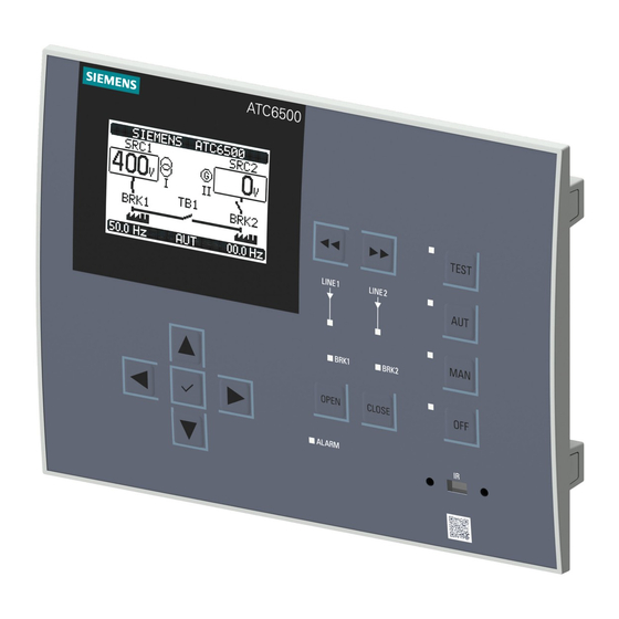
SENTRON ATC6500
Siemens SENTRON ATC6500 Manuals
Manuals and User Guides for Siemens SENTRON ATC6500. We have
1
Siemens SENTRON ATC6500 manual available for free PDF download: Manual
Siemens SENTRON ATC6500 Manual (256 pages)
Transfer switching equipment and load transfer switches 3KC transfer control device
Brand:
Siemens
| Category:
Control Unit
| Size: 19.73 MB
Table of Contents
Table of Contents
5
1 Introduction
11
About this Documentation
11
Product-Specific Information
12
Certification
12
Reference Documents
13
Advanced Training Courses
14
Technical Support
14
Safety Instructions
15
Security Information
15
Open Source Software
16
2 General Information
17
Features of the ATC6500 Transfer Control Device
17
Compatible Siemens SENTRON Switching Devices
19
3 Applications
21
Transfer Control
21
Network/Network Application
21
Network/Generator Application
22
Generator/Generator Application
22
Load Management with the ATC6500
22
Application A: 2S - 0T
23
Application B: 2S - 1T - PL
24
Application C: 2S - 1T - si
25
Application D: 2S - 1T - AI
26
Application O: 2S - NPL
27
Controlling the Switching Devices
28
Controlling Motor-Driven Circuit Breakers
29
Controlling Remotely Operated Transfer Switching Equipment
29
Controlling Contactors
30
Voltage Measurement
30
P02 General
31
P06 Source Lines
31
P08 Switch
31
P09 Source Line CHK
32
4 Product Description
35
Status Leds
36
Keys
37
Interface
37
Menu Navigation
38
Description of the Main Menu
38
Description of the Symbols
39
Navigation through the Main Menu
40
Display Pages of the ATC6500
40
Description of the Display Pages
40
Voltage L-L
41
L-N Voltage
41
Threshold Limits
42
Alarms Status
43
Statistics
43
Battery Status
44
Expansion Modules
44
Inputs/Outputs
45
Inputs
45
Outputs
45
Date/Time
46
Information
46
Event Log
47
Counter Cntx
48
User Limits Limx
48
Automatic Test
49
Setup Menu
49
Password
50
Commands Menu
50
Synchronoscope
51
Synchronization
51
Delta Voltages
52
Scrolling through the Display
52
5 Functions
53
Basic Functions
53
Setting the Real-Time Clock
53
Password Protection
54
Password Protection against Physical Access
54
Password Protection against Remote Access (Remote Password)
55
Entering the Password Via User Interface
55
Keypad Lock
57
Activation of the Keypad Lock by Means of a Programmable Input
57
Activation of the Keypad Lock by Means of a Key Combination on the Operator Panel
57
Expandability by Modules
58
Enabling Additional Resources
59
Inserting an Expansion Module
60
Behavior of the ATC6500 after Inserting a Module
61
Communication Comx
62
Alarms
63
Features of the Alarms
64
Alarm Description
65
Alarm Table
67
User Alarms Uax
69
Automatic Test
69
Enabling the Automatic Test
70
Simulation of Priority Source Failure (Test Mode)
71
Commands Menu
72
Executing a Command
72
Table of Commands
74
Event Log
75
Advanced Functions
76
Remote Variables Remx
76
User Limit Limx
77
Timer Timx
79
Counter Cntx
80
6 Installation
81
Dimensions for the Door Cutout
81
Installation of the ATC6500
82
7 Connection
85
Connection of the Power Supply for the ATC6500
85
Use of a DC Source / Battery
87
Power Supply Using a Dual Power Supply
89
Power Supply by Means of UPS
90
Power Supply by Means of Contactors
91
General Connection Drawings
92
Transfer between 2 Sources, with 2 Breakers
92
Transfer with 2 Circuit Breakers
93
Transfer with Remotely Operated Transfer Switching Equipment
94
Transfer with Contactors
96
Transfer between 2 Sources, with 3 Switching Devices
97
Transfer with 3 Circuit Breakers
99
Connection of Siemens SENTRON Switching Devices
103
Accessories for Switching Devices
103
Accessories for Mechanical Interlock
104
Technical Specifications of the Siemens SENTRON Switching Devices (IEC Only)
107
Typical Operating Times of the Siemens SENTRON Switching Devices (IEC Only)
109
Connection of 3VA Molded Case Circuit Breakers
111
(IEC Only)
111
Transfer between Two 3VA Molded Case Circuit Breakers, with Electrical Interlock
111
Transfer between Three 3VA Molded Case Circuit Breakers, with Electrical Interlock
113
Transfer between Three 3VA Molded Case Circuit Breakers, Without Electrical Interlock
115
Connection of 3VA27 Motor-Driven Molded Case Circuit Breakers (IEC Only)
117
Transfer between Two 3VA27 Molded Case Circuit Breakers, with Electrical Interlock
117
Transfer between Three 3VA27 Molded Case Circuit Breakers, with Electrical Interlock
119
Transfer between Three 3VA27 Molded Case Circuit Breakers, Without Electrical Interlock
121
Connection of the 3WL Air Circuit Breaker
123
Transfer between Two 3WL10 Air Circuit Breakers, with Electrical Interlock
123
Transfer between Three 3WL10 Air Circuit Breakers, with Electrical Interlock
125
Transfer between Three 3WL10 Air Circuit Breakers, Without Electrical Interlock
127
Connection of 3WL Air Circuit Breakers, FS I - III
129
Transfer between Two 3WL FS I-III Air Circuit Breakers, with Electrical Interlock
129
Transfer between Three 3WL Air Circuit Breakers FS I-III, with Electrical Interlock
131
Transfer between Three 3WL Air Circuit Breakers FSI-III, Without Electrical Interlock
133
Connection of 3WT8 Air Circuit Breakers
135
Transfer between Two 3WT8 Air Circuit Breakers, with Electrical Interlock
135
Transfer between Three 3WT8 Air Circuit Breakers, with Electrical Interlock
137
Transfer between Three 3WT8 Air Circuit Breakers, Without Electrical Interlock
139
8 Operation
141
Operating Modes of the ATC6500
141
Setting the Operating Mode
141
OFF Mode (OFF)
142
TEST Mode
142
Manual Mode (MAN)
142
Automatic Mode (AUT)
145
Inputs and Outputs of the ATC6500
146
Voltage Measuring Inputs
146
Digital Inputs Inpx
147
Table of Functions of the Digital Inputs
147
Digital Outputs Outx
150
Table of Functions of the Digital Outputs
152
Addressing the Expansion Modules with Digital Inputs/Outputs
154
Integrated RS485 Interface COM1
154
9 Parameterization
157
Parameterization Via the User Interface
157
Changing the Parameters
160
Parameterization Via the Powerconfig Software
160
Procedure for Parameterization Via Powerconfig
160
Parameterization Via the Front Interface
161
Parameterization Via the RS485 Interface or the Expansion Modules for Communication
162
Parameters
162
P01 - Settings
163
P02 - General
164
P03 - Password
167
P04 - Battery
168
P05 - Acoustic Alarms
169
P06 - Source Lines
170
P07 - Breakers
171
P08 - Switch
173
P09 - Control Thresholds of the Source Lines
176
P10 - Communications
179
P11 - Automatic Test
180
P12 - Digital Inputs
181
P13 - Digital Outputs
182
P14 - Miscellaneous
182
P15 - User Limit Thresholds Limx
183
P16 - Counter Cntx
184
P17 - Timer Timx
185
P21 - User Alarms
186
10 MODBUS Communication
187
General Information on MODBUS
187
MODBUS RTU Protocol
187
MODBUS Functions
188
Function 04: Read Input Register
189
Function 06: Preset Single Register
190
Function 07: Read Exception Status
190
Function 16: Preset Multiple Register
191
Function 17: Report Slave ID
192
Password Entry by Means of MODBUS
193
Data Library
194
Measured Values (Use with MODBUS Function 03 and 04)
194
Status Bits (Use with MODBUS Function 03 and 04)
196
Commands (Use with MODBUS Function 06)
201
Status of the ATC (Use with MODBUS Function 03 and 04)
203
Real-Time Clock (Use with MODBUS Function 04 and 06)
203
Reading the Event Log
204
Reading Parameters by Means of MODBUS
206
Changing Parameters by Means of MODBUS
207
11 Accessories
211
Expansion Modules
211
Expansion Module 4DI - 3KC9000-8TL60
212
Technical Specifications 4DI
214
Expansion Module 4DO - 3KC9000-8TL61
215
Technical Specifications 4DO
216
Expansion Module 2DI 2DO - 3KC9000-8TL62
217
Technical Specifications 2DI 2DO
218
Expansion Module 2DO - 3KC9000-8TL63
220
Technical Specifications 2DO
221
Expansion Module 2DI 2DO - 3KC9000-8TL64
222
Technical Specifications 2DI 2DO
223
Expansion Module Ethernet - 3KC9000-8TL75
225
Technical Specifications Ethernet
226
IP Protective Seal - 3KC9000-8TL68
227
USB Front Interface - 3KC9000-8TL73
227
12 Transfer
229
Transfer Types
229
Open Transition
229
IN-PHASE Transition
230
Transfer Sequence
231
Transfer Sequence for Application A: 2S - 0T
231
Transfer Sequence for Application B: 2S - 1T - PL
232
Transfer Sequence for Application C: 2S - 1T - si
233
Transfer Sequence for Application D: 2S - 1T - AI
234
Transfer Sequence for Application O: 2S - NPL
236
13 Technical Specifications
239
14 Dimension Drawings
243
ESD Guidelines
245
Electrostatic Sensitive Devices (ESD)
245
List of Abbreviations
247
Index
249
Advertisement
Advertisement
Related Products
Siemens SIDOOR ATD4 W Series
Siemens SIRIUS ACT 3SU1
Siemens A80485-1
Siemens MOBY I ASM 421
Siemens SITRANS AW 7MP3112 Series
Siemens AGM60.4A9
Siemens Add 7 AddFEM
Siemens SIRIUS ACT 3SU18 N Series
Siemens SIRIUS ACT 3SU140 E N Series
Siemens SIRIUS ACT 3SU14
Siemens Categories
Industrial Equipment
Controller
Control Unit
Oven
Washer
More Siemens Manuals
Login
Sign In
OR
Sign in with Facebook
Sign in with Google
Upload manual
Upload from disk
Upload from URL