Sign In
Upload
Manuals
Brands
Siemens Manuals
Measuring Instruments
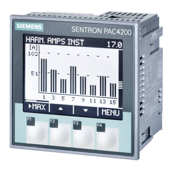
SENTRON PAC4200
Siemens SENTRON PAC4200 Power Meter Manuals
Manuals and User Guides for Siemens SENTRON PAC4200 Power Meter. We have
4
Siemens SENTRON PAC4200 Power Meter manuals available for free PDF download: Manual, Operating Instructions Manual
Siemens SENTRON PAC4200 Manual (252 pages)
Power Monitoring Device
Brand:
Siemens
| Category:
Measuring Instruments
| Size: 7.82 MB
Table of Contents
Manual
2
Table of Contents
3
Manual
8
SENTRON PAC4200 Manual, 09/2008, A5E02316180B-01
9
Manual
10
1 Introduction
11
Purpose of this Document
11
Orientation Aids
11
Components of the Product
12
Contents of the Data Carrier
12
Technical Support
12
Table 1- 1 Contacts in Your Region - Worldwide
13
Table 1- 2 Online Service and Support
13
Table 1- 3 Technical Support
13
Further Documentation
14
2 Safety Instructions
15
3 Description
17
Features
17
Table 3- 1 Device Versions
18
Measuring Inputs
21
Measured Variables
22
Table 3- 2 Available Connection Types
22
Table 3- 3 Display of the Measured Variables Depending on the Connection Type
25
Sliding Window Demand Values
28
Other Properties of Measured Variable Representation
29
Load Profile
29
Overview
29
Historical Load Profile
32
Table 3- 4 Historical Load Profile
32
Current Load Profile Data at the Communication Interfaces
33
Synchronization of the Load Profile
34
Additional Information about the Load Profile Data
35
Tariffs
36
Technical Features of the Supply Quality
36
Date and Time
40
Limit Values
40
Digital Inputs and Outputs
42
Ethernet Port
44
Slots for Expansion Modules
45
Serial Gateway
46
Insertion Openings
48
Password Protection
49
User-Definable Display of Measured Variables
50
Events
51
Table 3- 5 Meaning of the Symbols in the Events List
51
Table 3- 6 the Following Events Are Reported
52
4 Operation Planning
55
5 Installation
57
Unpacking
57
Insert Battery
58
Mounting on the Switching Panel
60
Tools
60
Mounting Dimensions
60
Installation Steps
60
Deinstalling
64
6 Connecting
67
Safety Notes
67
Connections
68
Connecting the Cables to the Terminals
74
Connection Examples
75
Grounding of the Ethernet Cable
82
Figure 6-22 Grounding of the Ethernet Cable
83
7 Startup
85
Overview
85
Apply the Supply Voltage
86
Table 7- 1 Connection of Supply Voltage
86
Parameterizing the Device
87
Procedure
87
Language
87
Date and Time
89
Voltage Input
90
Set the Connection Type
90
Table 7- 2 Available Connection Types
90
Measurement Using Voltage Transducers
91
Setting the Conversion Ratio of the Voltage Transducer
91
Setting the Voltage Input
93
Current Input
94
Setting the Conversion Ratio of the Current Transducer
94
Apply the Measuring Voltage
95
Apply the Measuring Current
95
Check the Displayed Measured Values
96
8 Operator Control
97
Device Interface
97
Displays and Operator Controls
97
Figure 8-2 Information Structure and Navigation
100
Displaying Measured Variables
104
Display of the "MAIN MENU
107
Display of the "SETTINGS" Menu
108
Table 8- 1 Assignments of the Function Keys in the "MAIN MENU
108
Device Settings Display
109
Table 8- 2 Assignments of the Function Keys in the "SETTINGS" Menu
109
Edit Mode of the Device Settings
110
Table 8- 3 Assignments of the Function Keys in the Device Settings Display
110
Table 8- 4 Assignments of the Function Keys in Edit Mode of the Device Settings
111
Operator Input Steps
112
Operator Input Steps in the Measured Variable Display
112
Operator Input Steps in the "MAIN MENU
113
Operator Input Steps in the "SETTINGS" Menu
114
Operator Input Steps in Device Settings Display
114
Operator Input Steps in Edit Mode of the Device Settings
115
Special Displays
116
Phasor Diagram
116
Table 8- 5 Symbols Used in the Phasor Diagram
116
Table 8- 6 Values in the Phasor Diagram
117
9 Parameterizing
119
Introduction
119
Parameterizing the Operator Interface
119
Groups of Settings
119
Device Information
120
Language and Regional Settings
121
Basic Parameters
121
Power Demand
125
Date/Time
126
Integrated I/Os
127
Communication
131
Display
132
Advanced
133
Figure 9-12 Effect of Delay and Hysteresis on Upper and Lower Limit Violations
136
External Modules
141
Password Management
141
Calling Password Management
142
Switch on Password Protection
142
Switch off Password Protection
143
Change Password
144
Password Lost - What to Do
145
10 Service and Maintenance
147
Calibration
147
Cleaning
147
Firmware Updates
147
Replacing the Battery
147
Figure 10-1 "CHANGE BATTERY
148
Figure 10-3 Battery Change
150
Repair
151
Disposal
151
11 Technical Data
153
Digital Outputs
156
Safety Regulations
162
Labeling
163
12 Dimension Drawings
165
Appendix
169
Measured Variables
169
A.1 Measured Variables
169
Load Profile
195
A.2 Load Profile
195
Modbus
196
Measured Variables Without a Time Stamp with the Function Codes 0X03 and 0X04
196
Table A- 1 Measured Variables Available Without a Time Stamp
196
A.3 Modbus
196
Structure - Digital Inputs Status and Digital Outputs Status with the Function Codes 0X01 and 0X02
203
Table A- 3 Structure - Digital Inputs Status and Digital Outputs Status
203
A.3.2 Structure - Digital Inputs Status and Digital Outputs Status with the Function Codes 0X01 and 0X02
203
Structure - Limit Values with the Function Codes 0X01 and 0X02
204
Structure - PMD Diagnostics and Status with the Function Codes 0X03 and 0X04
205
Measured Variables for the Load Profile with the Function Codes 0X03 and 0X04
206
Tariff-Specific Energy Values in Double Format with the Function Codes 0X03, 0X04, and 0X10
208
Tariff-Specific Energy Values in Float Format with the Function Codes 0X03 and 0X04
208
Table A- 2 Meaning of the Abbreviations in the "Access" Column
208
A.3.6 Tariff-Specific Energy Values in Double Format with the Function Codes 0X03, 0X04, and 0X10
208
Maximum Values with a Time Stamp and the Function Codes 0X03 and 0X04
209
Minimum Values with a Time Stamp and the Function Codes 0X03 and 0X04
213
Harmonics Without a Time Stamp with the Function Codes 0X03 and 0X04
216
Table A- 16 Harmonics of the Current
217
Table A- 17 Harmonics of the Phase-To-Phase Voltage
218
Harmonics with a Time Stamp and the Function Codes 0X03 and 0X04
220
Table A- 19 Harmonics of the Current
222
Configuration Settings with the Function Codes 0X03, 0X04, and 0X10
224
Value Range for Limit Source
230
Communication Settings with the Function Codes 0X03, 0X04, and 0X10
237
A.3.15 I&M Settings
239
Commands with the Function Code 0X06
239
MODBUS Standard Device Identification with the Function Code 0X2B
241
A.4 Correction Sheet
242
Correction Sheet
242
ESD Guidelines
243
Electrostatic Sensitive Devices (ESD)
243
List of Abbreviations
245
C.1 Abbreviations
245
100 C List of Abbrev Iations
247
Glossary
247
Index
251
Advertisement
Siemens SENTRON PAC4200 Manual (224 pages)
Power monitoring device
Brand:
Siemens
| Category:
Measuring Instruments
| Size: 4.84 MB
Table of Contents
Table of Contents
4
1 Introduction
8
Components of the Product
8
Latest Information
8
Security Information
10
2 Description
12
Performance Features
12
Measuring Inputs
17
Measured Variables
19
Sliding Window Demands
22
Averaging Measured Values (Aggregation)
23
Other Properties of Measured Variable Representation
23
Load Profile
24
Historical Load Profile
28
Current Load Profile Data at the Communication Interfaces
29
Synchronization of the Load Profile
30
Additional Information about the Load Profile Data
31
Tariffs
31
Technical Features of the Network Quality
32
Date and Time
34
Limit Values
35
Function of the Digital Inputs and Outputs
36
Digital Output
36
Digital Input
38
Ethernet Interface
39
Slots for Expansion Modules
40
Gateway
41
Insertion Openings
43
User-Definable Displays
44
3 Installation
46
Introduction
46
Inserting the Battery
48
Tools
49
Mounting on the Switching Panel
49
Mounting Dimensions
49
Installation Steps
50
Deinstallation
52
4 Connection
54
Safety Information
54
Connections
56
Connection Examples
59
Grounding of the Ethernet Cable
66
5 Commissioning
68
Overview
68
Applying the Supply Voltage
69
Parameterizing the Device
70
First Start-Up
70
Basic Parameters
71
Additional Settings
72
Applying the Measuring Voltage
72
Applying the Measuring Current
73
Checking the Displayed Measured Values
73
6 Operation
74
Device Interface
74
Displays and Operator Controls
74
Special Display Elements
75
Menu-Based Navigation
76
Measured Value Level
76
Main Menu Level
77
Setting Level
77
Editing Level
77
Control Keys
78
Special Displays
80
Phasor Diagram
80
Measurement of 1St to 64Th Harmonics for Voltage and Current
81
Events
83
Supporting Software
87
SENTRON Powermanager
87
SENTRON Powerconfig
88
Web Server
88
7 Parameterizing
90
Introduction
90
Parameterizing Via the User Interface
91
Device Information
92
Language/Regional
92
Basic Parameters
92
Power Demand
96
Date/Time
96
Integrated I/Os
98
Communication
102
Display
104
Advanced
105
Protection against Manipulation
112
Introduction
112
Password Protection
113
Hardware Write Protection
115
Device Access Control (IP Filter)
118
Configuring the Modbus TCP Port
120
8 Service and Maintenance
122
Calibration
122
Cleaning
122
Firmware Update
123
Replacing the Battery
124
Repair
127
Disposal
127
9 Technical Data
128
Labeling
139
10 Dimensional Drawings
142
Appendix
146
Load Profile
146
Modbus
146
Measured Variables Without a Time Stamp with the Function Codes 0X03 and 0X04
147
Structure - Digital Inputs Status and Digital Outputs Status with the Function Codes 0X01 and 0X02
154
Structure - Limit Values with the Function Codes 0X01 and 0X02
155
Structure - PMD Diagnostics and Status with the Function Codes 0X03 and 0X04
156
Measured Variables for the Load Profile with the Function Codes 0X03 and 0X04
157
Tariff-Specific Energy Values in Double Format with the Function Codes 0X03, 0X04, and 0X10
160
Tariff-Specific Energy Values in Float Format with the Function Codes 0X03 and 0X04
161
Maximum Values with a Time Stamp and the Function Codes 0X03 and 0X04
162
Minimum Values with a Time Stamp and the Function Codes 0X03 and 0X04
166
Odd Harmonics Without a Time Stamp with the Function Codes 0X03 and 0X04
169
Odd Harmonics with a Time Stamp with the Function Codes 0X03 and 0X04
171
Readout of Harmonic Components of All Harmonics with Function Codes 0X03, 0X04 and 0X14
173
Nth Harmonic Voltage L1
174
Nth Harmonic Voltage L2
174
Nth Harmonic Voltage L3
174
Readout of Averages (Aggregation) with Function Codes 0X03, 0X04 and 0X14
176
Configuration Settings with the Function Codes 0X03, 0X04, and 0X10
193
Value Range for Limit Source
202
Fundamental Current L1
206
Fundamental Current L2
206
Fundamental Current L3
206
3Rd Harmonic Current L1
206
3Rd Harmonic Current L2
206
3Rd Harmonic Current L3
206
Communication Settings with the Function Codes 0X03, 0X04, and 0X10
208
I&M Settings
211
Commands with the Function Code 0X06
212
MODBUS Standard Device Identification with the Function Code 0X2B
213
Comprehensive Support from a to Z
214
List of Abbreviations
216
Abbreviations
216
Glossary
218
Index
220
Siemens SENTRON PAC4200 Operating Instructions Manual (32 pages)
Power Monitoring Device
Brand:
Siemens
| Category:
Measuring Instruments
| Size: 2.58 MB
Table of Contents
Operating Instructions
4
Technical Data
5
Caractéristiques Techniques
8
Dati Tecnici
14
Características Técnicas
17
Technical Support
32
Advertisement
Siemens SENTRON PAC4200 Operating Instructions Manual (8 pages)
Brand:
Siemens
| Category:
Control Unit
| Size: 0.91 MB
Advertisement
Related Products
Siemens SENTRON PAC4220
Siemens SENTRON PAC3100
Siemens SENTRON PAC3200T
siemens SENTRON PAC2200
Siemens SENTRON PAC5100
Siemens SENTRON PAC5200
Siemens SENTRON PAC3200
Siemens SENTRON PAC3120
Siemens SENTRON PAC3220
Siemens SENTRON PAC2200CLP
Siemens Categories
Industrial Equipment
Controller
Control Unit
Oven
Washer
More Siemens Manuals
Login
Sign In
OR
Sign in with Facebook
Sign in with Google
Upload manual
Upload from disk
Upload from URL