Sign In
Upload
Manuals
Brands
Siemens Manuals
I/O Systems
Simantic ET 200S
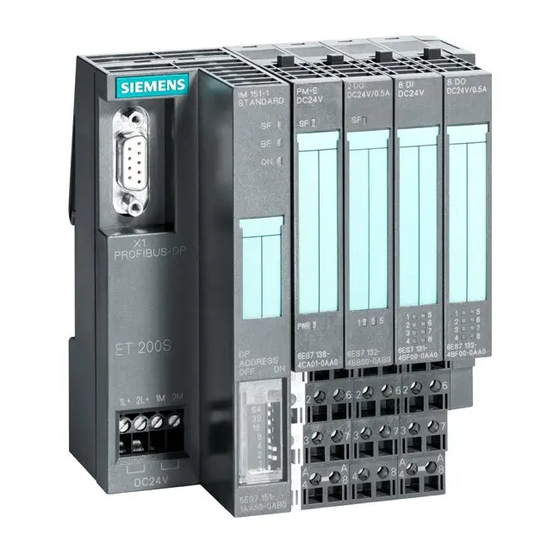
Siemens Simantic ET 200S Manuals
Manuals and User Guides for Siemens Simantic ET 200S. We have
1
Siemens Simantic ET 200S manual available for free PDF download: Manual
Siemens Simantic ET 200S Manual (274 pages)
Distributed I/O System
Brand:
Siemens
| Category:
I/O Systems
| Size: 7.68 MB
Table of Contents
Table of Contents
3
Manual, Edition 10/2005
8
1 Terminal Modules
9
Terminal Module TM-P15S23-A1, TM-P15C23-A1 and TM-P15N23-A1 (6ES7193-4Ccx0-0AA0)
10
Edition
10
Terminal Modules TM-P15S23-A0, TM-P15C23-A0 and TM-P15N23-A0 (6ES7193-4Cdx0-0AA0)
11
Edition
11
TM-P15S22-01, TM-P15C22-01 and TM-P15N22-01 Terminal Modules (6ES7193-4Cex0-0AA0)
12
TM-P30S44-A0 and TM-P30C44-A0 Terminal Modules (6ES7193-4Ckx0-0AA0)
13
TM-PF30S47-F1 Terminal Module for PM-D F DC24V Profisafe (3RK1903-3AA00)
15
TM-E15S26-A1, TM-E15C26-A1 and TM-E15N26-A1 Universal Terminal Modules (6ES7193-4Cax0-0AA0)
16
Terminal Module TM-E15S24-A1, TM-E15C24-A1 and TM-E15N24-A1 (6ES7193-4Cax0-0AA0)
17
TM-E15S24-01, TM-E15C24-01 and TM-E15N24-01 Terminal Modules (6ES7193-4Cbx0-0AA0)
19
TM-E15S23-01, TM-E15C23-01 and TM-E15N23-01 Terminal Modules (6ES7193-4Cbx0-0AA0)
20
Terminal Module TM-E15S24-AT and TM-E15C24-AT (6ES7193-4Clx0-0AA0)
21
TM-E30S46-A1 and TM-E30C46-A1 Universal Terminal Modules (6ES7193-4Cfx0-0AA0)
23
TM-E30S44-01 and TM-E30C44-01 Terminal Modules (6ES7193-4Cgx0-0AA0)
25
TM-C120S and TM-C120C Terminal Modules (6ES7193-4Dlx0-0AA0)
26
TE-U120S4X10 and TE-U120C4X10 Supplementary Terminal (6ES7193-4Flx0-0AA0)
27
Table 1-1 Potential Groups on the Supplementary Terminal
27
2 Power Modules
29
Configuring the Address Space
29
Parameters for Power Modules
30
Table 2-2 Parameters for Power Modules
30
PM-E 24 VDC Power Module (6ES7138-4CA01-0AA0)
31
PM-E 24-48 VDC Power Module (6ES7138-4CA50-0AA0)
34
PM-E 24-48 VDC/24-230 VAC Power Module (6ES7138-4CB10-0AB0)
37
Placing Power Modules and Connecting Them to Common Potential
40
Example of a Configuration: Terminal Modules for Power Modules
42
Table 2-3 Terminal Modules for Power Modules
42
Finding the Correct Power Module for an I/O Device
44
3 Digital Electronic Modules
45
Parameters for Digital Electronic Modules
45
Parameters for Digital Input Modules
45
Parameters for 4DI NAMUR
46
Table 3-2 Parameters for 4DI NAMUR
46
Parameters for Digital Output Modules
47
Table 3-3 Parameters for Digital Output Modules
47
Parameters of the Digital Electronic Modules
48
Hardware Interrupt
48
Input Delay
48
Trigger for Hardware Interrupt, Rising Edge
48
Pulse Stretching
49
Chatter Monitoring
50
2DI 24 VDC ST Digital Electronic Module (6ES7131-4BB01-0AA0)
52
4DI 24 VDC Standard Digital Electronic Module (6ES7131-4BD01-0AA0)
56
4DI 24 VDC/SRC Standard Digital Electronic Module (6ES7131-4BD51-0AA0)
59
2DI 24 VDC High Feature Digital Electronic Module (6ES7131-4BB01-0AB0)
63
4DI 24 VDC High Feature Digital Electronic Module (6ES7131-4BD01-0AB0)
67
4DI 24 VUC to 48 VUC High Feature Digital Electronic Module (6ES7131-4CD00-0AB0)
71
4DI NAMUR Digital Electronic Module (6ES7131-4RD01-0AB0)
75
Table 3-4 Diagnosis for Changeover Contacts
85
2DI 120 VAC Standard Digital Electronic Module (6ES7131-4EB01-0AB0)
86
2DI 230 VAC Standard Digital Electronic Module (6ES7131-4FB01-0AB0)
89
2DO 24 VDC/0.5 a Standard Digital Electronic Module (6ES7132-4BB01-0AA0)
92
Standard Digital Electronic Module 4DO 24 VDC/0.5 a (6ES7132-4BD01-0AA0)
96
2DO 24 VDC/0.5 a High Feature Digital Electronic Module (6ES7132-4BB01-0AB0)
100
2DO 24 VDC/2 a Standard Digital Electronic Module (6ES7132-4BB31-0AA0)
104
4DO 24 VDC/2 a Standard Digital Electronic Module (6ES7132-4BD31-0AA0)
108
2DO 24 VDC/2 a High Feature Digital Electronic Module (6ES7132-4BB31-0AB0)
112
2DO 24 VAC to 230 VAC Digital Electronic Module (6ES7132-4FB01-0AB0)
117
2RO no 24 VDC to 120 VDC/5 A, 24 VDC to 230 VAC/5 a Digital Electronic Module (6ES7132-4HB01-0AB0)
121
Table 3-5 Switching Capacity and Lifetime of the Relay Contacts
125
2RO NO/NC 24 VDC to 48 VDC/5 A, 24 VAC to 230 VAC/5 a Digital Electronic Module (6ES7132-4HB11-0AB0)
126
4 Analog Electronic Modules
131
Introduction
131
Analog Value Representation
131
Overview
131
Analog Value Representation for Measuring Ranges with SIMATIC S7
132
Table 4-1 Measured Values in the Event of Wire Break Dependent on Enabled Diagnostics
132
Table 4-2 Analog Value Representation (SIMATIC S7 Format)
132
Table 4-3 Measured Value Resolution of the Analog Values (SIMATIC S7 Format)
133
Measuring Ranges of the Analog Input Modules in SIMATIC S7 Format for Voltage, Current and Resistance-Type Sensors
134
Table 4-5 SIMATIC S7 Format: Measuring Ranges 1 V to 5 V, 0 Ma to 20 Ma, 4 Ma to 20 Ma
135
Table 4-6 SIMATIC S7 Format: Measuring Range ± 20 Ma
135
Measuring Range of the Analog Input Modules in SIMATIC S7 Format for Resistance Thermometers
136
Table 4-7 SIMATIC S7 Format: Measuring Ranges 150 Ω, 300 Ω, 600 Ω, 3000 Ω
136
Table 4-8 SIMATIC S7 Format: Measuring Ranges Pt 100, 200, 500, 1000 Standard in °C and °F
136
Table 4-9 SIMATIC S7 Format: Measuring Ranges Pt 100, 200, 500, 1000 Climatic in °C and °F
137
Table 4-10 SIMATIC S7 Format: Measuring Ranges ni 100, 120, 200, 500, 1000 Standard in °C and °F
137
Table 4-11 SIMATIC S7 Format: Measuring Ranges ni 100, 120, 200, 500, 1000 Climatic in °C and °F
138
Measuring Range of the Analog Input Modules in SIMATIC S7 Format for Thermocouples
139
Table 4-15 SIMATIC S7 Format: Measuring Range Type C in °C and °F
140
Table 4-17 SIMATIC S7 Format: Measuring Range Type J in °C and °F
141
Table 4-20 SIMATIC S7 Format: Measuring Range Type N in °C and °F
142
Output Ranges of the Analog Output Modules in SIMATIC S7 Format for Voltage and Current
143
Basics of Analog Value Processing
144
Connecting Measuring Sensors
144
Connecting Thermocouples
148
Table 4-26 Reference Junction Parameters
151
Wiring Unused Channels of the Analog Input Modules
153
Response of the Analog Modules During Operation and if Faults Occur
154
Influence of the Power Supply and the Operating Status on Analog Input and Output Values
154
Influence of the Value Range on the Analog Input
155
Influence of the Value Range on the Analog Output
155
Using the Shield Connection
156
Parameters for Analog Electronic Modules
156
Parameters for Analog Electronic Modules 2AI U Standard, 2AI I 2WIRE Standard, 4AI I 2WIRE Standard, 2AI I 4WIRE Standard
156
Parameters for Analog Electronic Modules 2AI U High Feature and 2AI I 2/4WIRE High Feature
157
Parameters for Analog Electronic Modules 2AI U High Speed, 2AI I 2WIRE High Speed and 2AI I 4WIRE High Speed
158
Parameters for Analog Electronic Modules 2AI RTD Standard, 2AI TC Standard and 2AI TC High Feature
159
Parameters for 2AI RTD High Feature Analog Electronic Module
160
Parameters for Analog Electronic Modules 2AO U Standard, 2AO U High Feature and 2AO I Standard, 2AO I High Feature
163
Parameters of the Analog Electronic Modules
164
2AI U Standard Analog Electronic Module (6ES7134-4FB01-0AB0)
167
2AI U High Feature Analog Electronic Module (6ES7134-4FB00-0AB0)
171
2AI U High Speed Analog Electronic Module (6ES7134-4FB51-0AB0)
175
2AI I 2WIRE Standard Analog Electronic Module (6ES7134-4GB01-0AB0)
179
4AI I 2WIRE Standard Analog Electronic Module (6ES7134-4GD00-0AB0)
183
2AI I 2WIRE High Speed Analog Electronic Module (6ES7134-4GB51-0AB0)
187
2AI I 4WIRE Standard Analog Electronic Module (6ES7134-4GB11-0AB0)
191
2AI I 2/4WIRE High Feature Analog Electronic Module (6ES7134-4MB00-0AB0)
195
2AI I 4WIRE High Speed Analog Electronic Module (6ES7134-4GB61-0AB0)
199
2AI RTD Standard Analog Electronic Module (6ES7134-4JB50-0AB0)
203
2AI RTD High Feature Analog Electronic Module (6ES7134-4NB51-0AB0)
207
2AI TC Standard Analog Electronic Module (6ES7134-4JB00-0AB0)
215
2AI RTD High Feature Analog Electronic Module (6ES7134-4NB01-0AB0)
220
2AO U Standard Analog Electronic Module (6ES7135-4FB01-0AB0)
225
2AO U High Feature Analog Electronic Module (6ES7135-4LB02-0AB0)
229
2AO I Standard Analog Electronic Module (6ES7135-4GB01-0AB0)
233
2AO I High Feature Analog Electronic Module (6ES7135-4MB02-0AB0)
236
5 Iq-Sense (6Es7138-4Ga00-0Ab0)
243
Features of 4 IQ-SENSE
243
Parameters for the 4 IQ-SENSE
244
Parameters
244
Group Diagnostics Parameter
245
Synchronization Group Parameter
245
Sensor Type Parameter
247
Switching Hysteresis Parameter
248
Time Functions, Time Values Parameters
249
Teach-In Disable Parameter
249
Control Interface (PIQ) and Feedback Interface (PII)
250
Basics of Control Interface (PIQ) and Feedback Interface (PII)
250
Standard
251
Enhanced
252
Technical Specifications
256
6 RESERVE Modules
259
Glossary
261
Index
271
Advertisement
Advertisement
Related Products
Siemens Simantic ET200SP
Siemens SIMATIC PROFINET
Siemens Simatic series
Siemens Simatic CFU
Siemens SICAM AI
Siemens SIMATIC PM-E
Siemens SIMATIC S7 EIP-200S
Siemens S55376-C104
Siemens S7-I/O
Siemens Simantic S7-1500
Siemens Categories
Industrial Equipment
Controller
Control Unit
Oven
Washer
More Siemens Manuals
Login
Sign In
OR
Sign in with Facebook
Sign in with Google
Upload manual
Upload from disk
Upload from URL