Sign In
Upload
Manuals
Brands
Siemens Manuals
Computer Hardware
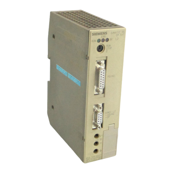
SIMATIC CP 541
Siemens SIMATIC CP 541 Manuals
Manuals and User Guides for Siemens SIMATIC CP 541. We have
1
Siemens SIMATIC CP 541 manual available for free PDF download: Manual
Siemens SIMATIC CP 541 Manual (147 pages)
Communications Processor
Brand:
Siemens
| Category:
Computer Hardware
| Size: 0.75 MB
Table of Contents
Edition
2
Table of Contents
5
1 Overview
9
Performance Features of the CP
10
Overview
10
Communication Modes
11
The CP 541 in the SIMATIC Environment
12
CP 541 in the SIMATIC Environment
12
View of the CP 541
13
View of the CP
13
LED Indicators of the CP 541
14
Mode Switch of the CP 541
14
Connectors and Terminals of the CP 541
14
Suitable Programmable Controllers for the CP 541
15
Connectable Programmable Controllers and Communication Modes; both Stations Connected to SINEC L2 Via CP
15
Connectable Programmable Controllers and Communication Modes
15
2 Communication Modes
17
PLC-PLC Connection
18
Address Conversion for PLC-PLC Connection
18
DP Connection
19
Address Conversion for DP Connection
19
Broadcast Via FDL Connection
20
Address Conversion for Broadcast
20
3 Installing and Connecting the CP 541
21
Installing the CP 541
22
Connecting the CP 541
23
Cable for Connecting the PLC and the CP
23
Components for SINEC L2
23
Isolation of Terminals
24
Starting up the CP 541
25
Operating States of the CP 541
26
Power on
26
Power on
27
STOP State
27
STOP State
28
Start
29
RUN State
30
4 Assigning Parameters to the CP 541 for the Connections
31
Configuring a PLC-PLC Connection
32
Configuring the Broadcast Mode
33
Configuring a DP Connection
34
5 CP 541 with S5-95F/S5-115F
37
Supported Failsafe Programmable Controllers
37
Communication Modes
38
Safety-Related PLC-PLC Connection
39
Address Conversion for the Safety-Related PLC-PLC Connection
39
Safety-Related Broadcast Via FDL
40
Address Conversion for Broadcast
40
Configuring Connections
41
Configuring a Safety-Related PLC-PLC Connection
42
Configuring a Non-Safety-Related PLC-PLC Connection
43
Configuring the Safety-Related Broadcast Mode
44
Safety Times
45
Local Cycle Time for CP 541
46
Calculating the Local Cycle Time
47
Condition for the SINEC L1 Safety Time for Receiving
50
Graphic Representation of Cycle Times
50
Setting the Safety Times
52
Configuration Example for Calculating the Local Cycle Times
54
Example of Verification of Safety Times
58
Redundant SINEC L2 Configuration
60
Schematic Configuration of SINEC L2 in Redundant Configuration
60
6 Diagnostics and Error Handling
61
Local Diagnostics with Leds
62
Indications of the RUN LED
62
Diagnostics Block
64
Structure of the Diagnostics Block
65
Assignments of the Data Words in DB2
65
Significance of DW0 in DB2
65
DB1 Errors
66
DB1 Error Codes
67
SINEC L2 Bus Errors
69
SINEC L1 Message Errors
70
Internal Errors
72
DP Diagnostic Message Using the Example of an IM 308-C with FB IM308C
73
Standard DIN E 19245, Part
73
Communications Processor CP
74
Structure of the Diagnosis
75
Structure of the Diagnostic Message
75
Structure of Station Status 1 (Byte 0)
76
Structure of Station Status 2 (Byte 1)
76
Contents of the DP Standard Section
76
Device-Related Diagnosis
78
Structure of Bytes 6 and 7 of the Diagnostic Message
78
Structure of the Device-Related Diagnosis
78
Example of Configuration
79
Example of a Diagnostic Call with IM308-C and FB IM308C
79
DP Diagnosis in the Programmable Controller
80
Technical Data
81
CP 541 Dimension Drawing
84
Optimizing SINEC L2
85
Parameters of DB1
89
Structure of DB1
90
C.1 Structure of DB1
90
Syntax of DB1
91
C.2 Syntax of DB1
91
General SINEC L2 Parameters - Block Identifier SL2
92
SL2 Parameters
92
Necessary Basic Parameters According to Station Status (STA
93
DP/FMS Bus Profile (in Bit Times
94
PROFIBUS-DP Bus Profile (in Bit Times
94
DP Bus Profile for IM 308-B (in Bit Times
94
User-Defined Bus Profile (in Bit Times
95
CP 541-Specific Parameters - Block ID COM
96
COM Parameters
96
DP Parameters - Block ID "DPS
98
DPS Parameters
98
C.5 DP Parameters – Block ID "DPS"
98
C.6 Default DB1
100
Default DB1
100
Default Values in DB1
101
Calculating the Token Rotation Time
102
Basic Load on SINEC L2 (in Bit Times
103
Example of Calculation of the Token Rotation Time
104
DP Parameter Assignment Message
107
Structure of the DP Standard Section of the
107
Structure of the Station Status in the Parameter Assignment Message
108
DP Configuring Message
109
Structure of Identifier Byte in Configuring Message
109
Definitions for the DP Master
111
Service Access Point (SAP) and PROFIBUS Services
113
PLC-PLC Connection
113
Meanings of Service Access Points (Saps
113
PROFIBUS Services
114
Configuration for a PLC-PLC Connection
116
DP Connection
122
Configuration of a DP Connection
122
H.2 DP Connection
122
Safety-Related PLC-PLC Connection: S5-95F - S5-115F
126
Configuration for a Safety-Related PLC-PLC Connection
126
Advertisement
Advertisement
Related Products
Siemens CP 5613 A3
Siemens CP 5614 A3
Siemens SIMATIC NET CP 5603
Siemens SIMATIC NET CP 5512
Siemens SIMATIC NET CP 5622
Siemens SIMATIC CP 340
Siemens CPU 412
Siemens CPU 416-2
Siemens CPU 31xC Series
Siemens CPU 317-2 PN/DP
Siemens Categories
Industrial Equipment
Controller
Control Unit
Oven
Washer
More Siemens Manuals
Login
Sign In
OR
Sign in with Facebook
Sign in with Google
Upload manual
Upload from disk
Upload from URL