Sign In
Upload
Manuals
Brands
Siemens Manuals
Computer Hardware
Simatic M7-400
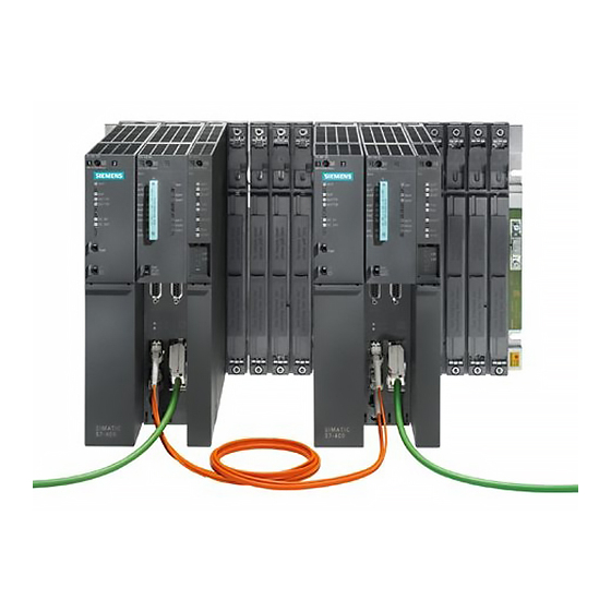
User Manuals: Siemens Simatic M7-400 PLC Unit
Manuals and User Guides for Siemens Simatic M7-400 PLC Unit. We have
3
Siemens Simatic M7-400 PLC Unit manuals available for free PDF download: Reference Manual, Installation Manual, Hardware And Installation Manual
Siemens Simatic M7-400 Reference Manual (638 pages)
Programmable Controllers Module Specifications
Brand:
Siemens
| Category:
Computer Hardware
| Size: 3.99 MB
Table of Contents
Table of Contents
11
Edition
2
Power Supply Modules 4
11
Digital Modules
12
Analog Modules
13
Cable Duct and Fan Subassemblies
15
Interface Modules
15
PROFIBUS DP Master Interface IM 467/IM 467 FO
15
Interface Submodules
16
M7-400 Expansions
16
RS 485 Repeater
16
Table of Contents
17
Terminal Assignment and Block Diagram of the SM
20
DO 16 X 20-125 VDC/1.5 a
23
DO 32 X 24 VDC/0.5 a
23
Terminal Assignment Diagram of the SM
20
Table of Contents
24
VDC
25
1 General Technical Specifications
29
Standards and Approvals
30
Use in an Industrial Environment
30
Products that Fulfill the Requirements of the Low-Voltage Directive
31
Power Supply to the Backup Battery
34
Electromagnetic Compatibility
37
Interference Emission of Electromagnet Fields
39
Interference Emission Via the Mains AC Power Supply
39
Shipping and Storage Conditions for Modules
40
Shipping and Storage Conditions for Modules and Backup Batteries
40
Mechanical and Ambient Climatic Conditions for Operating the S7-400/M7-400
42
Mechanical Conditions
42
Ambient Mechanical Conditions for the MSM 478 Mass Storage Module in
43
Ambient Mechanical Conditions Test
43
Ambient Climatic Conditions for the S7-400
43
Power Supply Modules for Use at up to + 1500 M
44
Ambient Climatic Conditions for the M7-400
45
Information on Insulation Tests, Protection Class and Degree of Protection
46
Test Voltages
46
Using S7-400 in a Zone 2 Explosion-Risk Area
47
Weitere Informationen
48
Further Information
50
2 Racks
71
Function and Structure of the Racks
72
Structure of a Rack with 18 Slots
72
The Racks UR1; (6ES7400-1TA01-0AA0) and UR2; (6ES7400-1JA01-0AA0)
73
Dimensions of the UR1 18-Slot or UR2 9-Slot Rack
73
The Rack UR2-H; (6ES7400-2JA00-0AA0)
75
Rack Dimensions
75
The Rack CR2; (6ES7401-2TA01-0AA0)
77
CR2 Rack
77
The Rack CR3; (6ES7401-2TA01-0AA0)
78
CR3 Rack
78
The Racks ER1; (6ES7403-1TA01-0AA0)
79
And ER2; (6ES7403-1JA01-0AA0)
79
ER1 Rack with 18 Slots and ER2 Rack with 9 Slots
80
3 Power Supply Modules
81
Redundant Power Supply Modules
81
Common Characteristics of the Power Supply Modules
82
Compliance with the NAMUR Recommendation
83
Redundant Power Supply Modules
84
Backup Battery (Option)
86
Controls and Indicators
88
Controls and Indicators on the PS 407 20A Power Supply Module
88
INTF, DC 5V, DC 24 V Leds
89
BAF, BATTF Leds
89
BAF, BATT1F, BATT2F Leds
89
Function of the Operator Controls of the Power Supply Modules
91
Error Messages of the Power Supply Modules
93
Fault/Error Messages Via Leds
93
INTF, DC5V, DC24V Leds
93
BAF, BATTF; BATT INDIC Leds on BATT
96
BAF, BATT1F, BATT2F; BATT INDIC Leds on 1BATT
97
BAF, BATT1F, BATT2F; BATT INDIC Leds on 2BATT
98
Controls and Indicators of the PS 407 4A
99
Power Supply Module PS 407 4A; (6ES7407-0DA00-0AA0)
99
Controls and Indicators of the PS 407 4 a
101
Power Supply Module PS 407 4A; (6ES7407-0DA01-0AA0)
101
Controls and Displays of the PS 407 10A and PS 407 10A R
103
Power Supply Modules PS 407 10A; (6ES7407-0KA01-0AA0) and PS 407 10A R; (6ES7407-0KR00-0AA0)
103
Controls and Displays of the PS 407 20A
106
Power Supply Module PS 407 20A; (6ES7407-0RA00-0AA0)
106
Controls and Indicators of the PS 407 20 a
108
Power Supply Module PS 407 20A (6ES7407-0RA01-0AA0)
108
Controls and Indicators of the PS 405 4 a
110
Power Supply Module PS 405 4A; (6ES7405-0DA00-0AA0)
110
S7-400, M7-400 Programmable Controllers Module Specifications A5E00069467-07
110
Controls and Indicators of the PS 405 4 a
112
Controls and Indicators of the PS 405 10 a
114
Controls and Displays of the PS 405 10A and PS 405 10A R
116
Controls and Indicators of the PS 405 20 a
118
Controls and Indicators of the PS 405 20 a
120
Chapter Overview
124
Digital Input Modules: Characteristics at a Glance
125
Digital Output Modules: Characteristics at a Glance
126
Relay Output Module: Characteristics at a Glance
126
Sequence of Steps from Choosing to Commissioning the Digital Module
127
Static and Dynamic Parameters of the Digital Modules
128
Diagnostic Messages of the Digital Modules, Causes of Errors and Remedial Measures
133
Diagnostic Messages of the Digital Modules
134
Input Characteristic Curve for Digital Inputs
138
Terminal Assignment and Block Diagram of the SM 421; DI 16 X 24 VDC
143
Terminal Assignment and Block Diagram of the SM 421; DI 32 X 24 VDC
143
Terminal Assignment and Block Diagram of the SM
146
24 VDC
146
Terminal Assignment Diagram for the Redundant Supply
147
How the Input Values Depend on the Operating Mode of the CPU
151
How the Input Values Are Affected by Faults and by the Parameter Assignment of the 24 VDC
152
Terminal Assignment Diagram for the Redundant Supply
156
How the Input Values Depend on the Operating Mode of the CPU and on the Supply Voltage L+ of the SM
160
How the Input Values Are Affected by Faults and by the 24 VDC
161
24/60 Vuc
166
Circuit as for Active High or Active Low Input
171
Terminal Assignment and Block Diagram of the SM
179
VDC
183
Parameters of the SM 421; DI
191
Terminal Assignment and Block Diagram of the SM
196
VDC
196
Terminal Assignment and Block Diagram of the SM
214
Common Features of the Interface Modules
364
Using Simatic S5 Expansion Units in an S
386
Rules for Connecting S5 Expansion Units
387
Operator Controls and Indicators
388
Installing and Connecting the IM
390
Setting the Operating Modes of the IM
392
Configuring S5 Modules for Operation in the S
394
Pin Assignments of the 721 Connecting Cable
395
Terminating Connector for IM
397
Technical Specifications (6Es7463–2Aa00–0Aa)
398
Indicators and the Mode Selector
402
Operation
405
Bus Connector
406
Connection to Profibus Dp
406
Connecting a Fiber-Optic Cable to the IM 467 Fo
408
Technical Specifications
410
Technical Specifications of the IM 467 Fo
411
Cable Duct and Fan Subassemblies
413
Fan Monitoring in the Fan Subassemblies
414
Cable Duct; (6Es7408-0Ta00-0Aa)
416
The 24 VDC Fan Subassembly; (6Es7408-1Ta00-0Xa)
419
Rs 485 Repeater
421
Terminal Connection Diagram
425
Cpus for M
429
Performance Features
430
Function Elements
432
Status and Fault Leds
434
Memory Cards
436
Mode Selector Switch
437
Submodule Receptacles for Interface Submodules
439
Memory Submodules Suitable for the Main Memory
441
Multipoint Interface (Mpi)
443
The Bios Setup
444
Bios Power up
445
Bios Hot Keys
447
Operator Inputs in the Bios Setup
448
Opening and Exiting the Bios Setup
451
Setup Page "User Help
452
Setup Page "If Modules
453
Setup Page "Timeout Function
457
Setup Page "Security
458
Setup Page "Date and Time
460
Setup Page "Floppy/Card
463
Setup Page "Boot Options
464
Setup Page "System
466
Exm 478 Expansion Module; (6Es7 478-2Ac00-0Ac)
476
Addressing the Exm 478 Expansion Module
477
Interrupt Assignments, Signal Switching Exm
483
Technical Specifications of the Exm 478 Expansion Module
484
Atm 478 at Adapter Module; (6Es7 478-2Ca00-0Ac)
485
Pin Assignments of the at Module
486
Technical Specifications of the Atm 478 at Adapter Module
489
Lpt1 Parallel Port
493
Technical Specifications of the Msm 478 Mass Storage Module
495
Interface Submodules
497
Interface Submodules Overview
498
Submodule Ids and Insertion Rules
500
Pin Assignments
502
Addressing, Interrupts, and Submodule ID
503
Digital Input Function
522
Acknowledgment Register
523
Digital Output Function
523
Interrupt Enable Register
524
Interrupt Register
524
Selection Register Falling Edge
525
Selection Register Rising Edge
525
Mode Register
526
Pin Assignments and Terminal Connection Diagram
530
Circuit Block Diagram
531
Connecting Measured Value Sensors to Analog Inputs
533
Conversion Time and Cycle Time of the Analog Input Channels
540
Electrical Installation
542
Starting up the if 961-Aio Interface Submodule
542
Analog Output Function
543
Analog Input Function
544
Individual Start of an Adc Channel
545
Cyclic Conversion of the Adc Channels
546
Analog Inputs
547
Analog Outputs
548
Diagnostics, Interrupts, and Submodule ID
549
What Can the If961-Ct1 Interface Submodule Do
553
Parameters of the Digital Input Modules
566
Parameters of the Digital Output Modules
569
List of Abbreviations
603
Advertisement
Siemens Simatic M7-400 Installation Manual (316 pages)
Brand:
Siemens
| Category:
Controller
| Size: 2.79 MB
Table of Contents
A5E00069481
3
Table of Contents
11
Memory Card
17
Removing the Cover
17
1 Product Overview
21
2 Installing the S7-400
27
Assembling an S7-400
28
Rack Fitted with Modules in the S7-400 System
28
Assembling the Central Rack (CR) and Expansion Rack (ER)
32
Segmented CR
34
Subdivided CR
35
Mounting and Grounding the Racks
36
Chassis Terminal Connection in the Non-Isolated Configuration
42
Methods of Ventilation
45
Changing the Ventilation with the Cable Duct and Fan Subassembly
47
Installing the Fan Subassembly
49
Installing the Cable Duct
51
Choosing and Setting up Cabinets with the S7-400
52
Types of Cabinet
53
Max. Cabinet Ambient Temperature as a Function
54
Rules for the Arrangement of Modules
56
Modules in the Different Racks
56
Fitting Memory Cards in the CPU
57
Fitting Memory Cards in the Cpus
58
Installing Modules in a Rack
59
Removing the Cover
60
Attaching the Modules
61
Screwing the Modules in Place
61
Inserting the Key in the CPU
62
Marking the Modules with Slot Labels
63
Fitting a Slot Label
63
Methods of Expansion and Networking
64
5 Networking
64
Starting up
64
Accessories
65
Accessories for Modules and Racks
65
3 Addressing the S7-400
67
Geographical and Logical Addresses
68
How to Determine the Default Address of a Module
70
How to Determine the Default Address of a Channel
72
4 Wiring the S7-400
75
Supplying Power to Modules
76
Choosing the Power Supply Module
77
Choosing the Load Current Power Supply
78
Assembling an S7-400 with Process I/Os
79
VDE Specifications for Assembling a Programmable Controller
80
Operating the S7-400 from a Grounded Supply
81
Assembling an S7-400 with Grounded Reference Potential (M)
82
An S7-400 Configured with Grounded Reference Potential
82
Assembling an S7-400 with Ungrounded Reference Potential (Ungrounded Configuration)
83
An S7-400 Configured with Ungrounded Reference Potential
83
Assembling an S7-400 with Isolated Modules
85
Simplified Representation of Configuration with Isolated Modules
86
Parallel Wiring of Digital S7-400 Outputs
87
Parallel Wiring of a Digital Output with Different Rated Load Voltages
87
Parallel Wiring of a Digital Output with Identical Rated Load Voltages
87
Grounding
88
Methods of Protective Grounding
88
Grounded Connection Load Voltage
89
Interference-Free Configuration for Local and Remote Connections
90
Shielding and Grounding the Connecting Cable for a Remote Connection
91
Wiring Rules
92
Setting the VAC Power Supply Module to the Line Voltage
93
Setting the Voltage Selector
94
Wiring the Power Supply Module
95
Disconnecting Power Supply Connector
95
Wiring the Power Supply Connector
97
Plugging the Power Supply Connector
98
Wiring the Signal Modules
99
Preparing to Wire the Front Connector
100
Wiring the Front Connector, Crimp Snap-On Terminals
101
Wiring a Front Connector with Crimp Snap-On Terminals
101
Wiring the Front Connector, Screw-Type Terminals
102
Wiring a Front Connector with Screw-Type Terminals
102
Wiring the Front Connector, Spring-Type Terminals
103
Wiring a Front Connector with Spring-Type Terminals
103
Principle of the Spring Contact
104
Fitting the Strain Relief
105
Fitting a Strain Relief (Viewed from Below)
105
Labeling a Front Connector
106
Fitting a Label in the Front Connector
107
Fitting the Front Connector
110
Front Connector Coding Elements
110
Attaching the Front Connector
111
Screwing on the Front Connector
112
Interconnecting the CR and er(S)
113
Plugging a Connecting Cable into a Send IM
113
Connection between a Send IM and Two Receive Ims
114
Setting the Fan Subassembly to the Line Voltage and Wiring It
115
Wiring the Fan Subassembly
116
Routing Cables Using Cable Ducts or Fan Subassemblies
117
Routing Cables Using Fiber-Optic Cables
117
Networking
119
Configuring a Network
120
Fundamentals
121
Communication between Programming Device/Operator Panel and a Module Without MPI
123
Data Exchange
124
Rules for Configuring a Network
125
Terminating Resistor on Bus Connector
127
Terminating Resistor on RS 485 Repeater
127
Terminating Resistor on MPI Network
128
Example of an MPI Network
129
Example of a PROFIBUS DP Network
130
Example with CPU
131
Programming Device Access Beyond Network Limits
132
Cable Lengths
133
Permitted Cable Length of a Segment in an MPI Network
133
Permitted Cable Length of a Segment in the PROFIBUS-DP Network
133
Depending on the Transmisson Rate
133
Lengths of Spur Lines Per Segment
134
Configuration of an MPI Network
135
PROFIBUS-DP Bus Cables
136
Bus Connectors
137
Bu S Connector
137
Strip Bus Cable
138
Inserting Cores into the Screw Termninal Blocks
139
Switch on Terminating Resistant
140
RS 485 Repeater
141
Turning Back Braided Shield over Cable
142
PROFIBUS-DP Network with Fiber-Optic Cables
143
Optical PROFIBUS-DP Network with Nodes that Have an Integrated Fiber-Optic Cable Interface
144
Fiber-Optic Cables
145
Features of the Fiber-Optic Cables
145
Simplex Connectors and Connector Adapter
147
Order Numbers - Fiber-Optic Cables
147
Order Numbers - Simplex Connectors and Connector Adapters
148
Simplex Connectors and a Special Connector Adapter for the IM 153-2 FO and IM 467 FO (Installed)
148
Connecting a Fiber-Optic Cable to the PROFIBUS Device
149
Permissible Cable Lengths on the Optical PROFIBUS-DP Network
149
6 Starting up
151
Recommended Procedure for First Startup
152
Checklist to be Used before Switching on for the First Time
153
Setting the Battery Monitoring Switch
155
Connecting a Programming Device (PG) to an S7-400
155
Switching on an S7-400 for the First Time
156
Resetting the CPU with the Mode Selector Switch
157
Cold, Warm, and Hot Restarts with the Mode Selector Switch
160
Inserting a Memory Card
161
Inserting a Memory Card in a CPU
162
Inserting a Backup Battery (Option)
163
Starting up a PROFIBUS-DP Subnet
167
Inserting Interface Submodules in the CPU
169
7 Maintenance
171
Replacing the Backup Battery
172
Replacing a Power Supply Module
174
Replacing Cpus
175
Replacing Digital or Analog Modules
177
Changing the Fuses in the Digital Modules
179
Replacing Interface Modules
181
Replacing the Fuse of the Fan Subassembly
183
Replacing Fans in the Fan Subassembly During Operation
184
Replacing the Filter Frame of the Fan Subassembly During Operation
186
Replacing the Power Supply PCB and Monitoring PCB of the Fan Subassembly
188
Replacing Memory Cards
189
Fitting Memory Cards in the Cpus
190
Memory Card
191
Replacing Interface Submodules
192
Inserting an Interface Submodule in a CPU
193
8 Assembling the M7-400
195
Mechanical Configuration
196
Sequence in the Module Subassembly
197
Possible Applications of the M7-400 Modules
197
Dimensions of Modules in the M7-400 System
198
Addressing the M7-400 Modules
199
Electrical Configuration
200
Installing the M7-400
202
Checklist for Installation
203
Module Accessories
204
Accessories for Modules and Racks
204
Fitting Memory Cards in the CPU
205
Fitting Memory Cards in the Cpus
206
Installing Interface Submodules
207
Inserting an Interface Submodule in an Expansion Module
208
Fitting the Short at Card
209
Fitting an at Card in the ATM 478 at Adapter Module
210
Assembling Expansion Modules on a Central Rack
211
Locations of the Expansion Socket and Plug
212
EXM 478 Expansion Module Fitted with Connecting Clips
213
Removing the Cover
214
Interconnecting a CPU and Expansion Modules
215
Module Assembly Comprising CPU and Expansion Modules
216
Connecting Clip
217
Attaching a Module Assembly Comprising CPU and Expansion Modules and Swinging It into Position
219
Screwing the Modules on
220
Inserting the Key in the CPU
221
Inserting/Removing a Memory Card
222
Connecting a Module Assembly
223
Assembling an MPI Subnet or PROFIBUS-DP Subnet
224
Example of a Configuration with the CPU in an MPI Subnet and PROFIBUS-DP Subnet
225
Preparing for Operation
226
Connecting the Operator Panels and I/O Devices
227
Maximum Cable Lengths for Operator Panels and I/O Devices
229
Connecting a Programming Device (PG) to the COM Interface
230
Null Modem Cable for Connecting a CPU Via if to the COM Interface
231
Null Modem Cable for Connecting a CPU Via if to the COM Interface of a Programming Device with 25-Pin Sub. D Male Connector
231
Pin Assignments of the Cable for Connecting a CPU Via if to the COM Interface of a Programming Device with 9-Pin Sub. D Male Connector
232
Connecting a Programming Device (PG) to the M7-400
233
Connecting a Programming Device (PG) to Two or more Nodes
234
Connecting a Programming Device to Two or more M7-400S
235
Connecting a Programming Device to an M7-400 Subnet
236
Connecting a Programming Device (PG to Ungrounded Nodes of an MPI Subnet
237
Starting up a PROFIBUS-DP Subnet
238
Checking the Status and Error Indicators
239
Replacing Modules and Submodules/Cards
240
Replacing an Interface Module
241
Removing an Interface Submodule from the Card Slot of an Expansion Module
242
Replacing the CPU or Expansion Modules of a Module Assembly
243
Unscrewing Modules
244
Swinging a Module Assembly out and Lifting It up and out
245
Removing the Connecting Clips from the Module to be Replaced
246
Separating the Modules, for Example When the Mass Storage Module Is to be Replaced
247
Replacing Memory Cards in a CPU
248
Removing Memory Cards from the Cpus
249
Replacing a Short at Card
250
Removing an at Card from the ATM 478 at Adapter Module
251
Assembling and Installing Systems
254
A.1 General Rules and Regulations for Operating the S7-400
254
Principles of System Installation for EMC
257
Installation of Programmable Controllers for EMC
261
Examples of EMC-Compatible Assembly
262
Key for Example 1
263
A.5 Shielding Cables
265
Shielding Cables
265
A.6 Equipotential Bonding
267
Equipotential Bonding
267
A-5 Routing Equipotential Bonding Conductor and Signal Line
268
Cabling Inside Buildings
269
Cabling Inside Buildings
270
Cabling Outside Buildings
271
Lightning Protection and Overvoltage Protection
272
Lightning Protection Zone Concept
273
A.9.2 Rules for the Transition between Lightning Protection Zones 0 and 1
275
High-Voltage Protection of Cables with the Help
275
Rules for the Transitions between Lightning Protection Zones 1 <-> 2 and Greater
277
Low-Voltage Protection Components for Lightning Protection Zones 1
278
Surge Protection Components for Lightning Protection Zones 2
279
Sample of a Surge Protection Circuit for Networked S7-400 Plcs
280
Example of a Circuit Conforming to Lightning Protection Requirements (Legend to Figure A-7)
281
How to Protect Digital Output Modules against Inductive Surge
282
Safety of Electronic Control Equipment
284
Interference-Free Connection of Monitors
286
A-11 Shielding and Grounding with a Great Distance between Monitor and Programmable Controller
288
Guidelines for Handling Electrostatically-Sensitive Devices (ESD)
290
What Is ESD
290
B.1 What Is ESD?
290
Electrostatic Charging of Persons
291
General Protective Measures against Electrostatic Discharge Damage
292
Siemens Simatic M7-400 Hardware And Installation Manual (298 pages)
Brand:
Siemens
| Category:
Controller
| Size: 3.97 MB
Table of Contents
3 Simatic
1
Table of Contents
1
Manual
3
Product Overview/Installing the S7-400
9
Addressing the S7-400
9
Installing the S7-400
9
Product Overview
9
Wiring the S7-400
9
Networking
10
Assembling the M7-400
11
Maintenance
11
Starting up
11
1 Product Overview
13
2 Installing the S7-400
21
Assembling an S7-400
22
Assembling the Central Rack (CR) and Expansion Rack (ER)
26
Segmented CR
28
Mounting and Grounding the Racks
29
Chassis Terminal Connection in the Non-Isolated Configuration
34
Methods of Ventilation
36
Changing the Ventilation with the Cable Duct and Fan Subassembly
38
Installing the Fan Subassembly
40
Installing the Cable Duct
42
Choosing and Setting up Cabinets with the S7-400
43
Rules for the Arrangement of Modules
47
Installing Modules in a Rack
48
Marking the Modules with Slot Labels
52
Methods of Expansion and Networking
53
Accessories
54
3 Addressing the S7-400
55
Geographical and Logical Addresses
56
How to Determine the Default Address of a Module
58
How to Determine the Default Address of a Channel
60
4 Wiring the S7-400
63
General Rules and Regulations for Operating the S7-400
64
Supplying Power to Modules
67
Choosing the Power Supply Module
68
Choosing the Load Current Power Supply
69
Assembling an S7-400 with Process I/Os
70
Assembling an S7-400 with Grounded Reference Potential (0 V)
72
(Ungrounded Configuration)
73
Assembling an S7-400 with Grounded Reference Potential M
73
Assembling an S7-400 with Ungrounded Reference Potential
73
Assembling an S7-400 with Isolated Modules
75
Shielding Cables
77
Equipotential Bonding
79
Protection against Inductive Surge Voltages
81
Grounding
83
Interference-Free Configuration for Local and Remote
85
Connections
85
Wiring Rules
87
Setting the VAC Power Supply Module to the Line Voltage
89
Wiring the Power Supply Module
90
Wiring the Signal Modules
94
Wiring the Front Connector, Crimp Snap-On Terminals
96
Wiring the Front Connector, Screw-Type Terminals
97
Wiring the Front Connector, Spring-Type Terminals
98
Fitting the Strain Relief
100
Labeling a Front Connector
101
Fitting the Front Connector
103
Interconnecting the CR and er(S)
106
Setting the Fan Subassembly to the Line Voltage and Wiring It
108
Routing Cables Using Cable Ducts or Fan Subassemblies
109
Routing Cables Using Fiber-Optic Cables
110
Interference-Free Configuration for Local and Remote Connections
85
5 Networking
111
Configuring a Network
112
Fundamentals
113
Rules for Configuring a Network
117
Cable Lengths
125
PROFIBUS-DP Bus Cables
128
Bus Connectors
129
RS 485 Repeater
133
PROFIBUS-DP Network with Fiber-Optic Cables
135
Simplex Connectors and Connector Adapter
139
Connecting a Fiber-Optic Cable to the PROFIBUS Device
141
6 Starting up
143
Recommended Procedure for First Startup
144
Checks Prior to Switching on for the First Time
145
Connecting a Programming Device (PG) to an S7-400
147
Switching on an S7-400 for the First Time
148
Resetting the CPU with the Mode Selector Switch
149
Cold, Warm, and Hot Restarts with the Mode Selector Switch
152
Inserting a Memory Card
153
Inserting a Backup Battery (Option)
155
Starting up a PROFIBUS-DP Subnet
159
Fitting Memory Cards in the CPU
161
Installing Interface Submodules (CPU 417 and 417 H)
163
7 Maintenance
165
Replacing the Backup Battery
166
Replacing a Power Supply Module
168
Replacing Cpus
169
Replacing Digital or Analog Modules
171
Changing the Fuses in the Digital Modules
173
Replacing Interface Modules
175
Replacing the Fuse of the Fan Subassembly
177
Replacing Fans in the Fan Subassembly During Operation
178
Replacing the Filter Frame of the Fan Subassembly During Operation
180
Fan Subassembly
182
Replacing the Power Supply PCB and Monitoring PCB of the
182
8 Assembling the M7-400
183
Mechanical Configuration
184
Addressing the M7-400 Modules
186
Electrical Configuration
187
Installing the M7-400
189
Checklist for Installation
190
Module Accessories
191
Fitting Memory Cards in the CPU
192
Installing Interface Submodules
194
Fitting the Short at Card
196
Assembling Expansion Modules on a Central Rack
198
Installing a Module Assembly in the Rack
205
Inserting/Removing a Memory Card
209
Connecting a Module Assembly
210
Assembling an MPI Subnet or PROFIBUS-DP Subnet
212
Connecting the Operator Panels and I/O Devices
215
Connecting a Programming Device (PG) to the M7-400
221
Connecting a Programming Device (PG) to Two or more Nodes
222
Subnet
223
Starting up a PROFIBUS-DP Subnet
226
Checking the Status and Error Indicators
227
Replacing an Interface Module
229
Replacing the CPU or Expansion Modules of a Module Assembly
231
Replacing a Short at Card
238
Assembling and Installing Systems
242
Principles of System Installation for EMC
242
Installation of Programmable Controllers for EMC
246
Cabling Inside Buildings
250
Cabling Outside Buildings
253
Lightning Protection and Overvoltage Protection
254
Rules for the Transition between Lightning Protection Zones 0 and 1
257
Rules for the Transitions between Lightning Protection Zones Greater than 0 <->1
259
Example Circuit for Surge Protection of Networked S7-400S
261
Interference-Free Connection of Monitors
263
Guidelines for Handling Electrostatically-Sensitive Devices (ESD)
267
What Is ESD
268
Electrostatic Charging of Persons
269
General Protective Measures against Electrostatic Discharge Damage
270
Siemens Worldwide
271
Glossary
275
Index
294
Advertisement
Advertisement
Related Products
Siemens Simatic S7-400
Siemens SIMATIC CP 340
Siemens SIMATIC NET CP 243-1 IT
Siemens Simatic VS 710
Siemens SIMATIC PCS 7 OSx
Siemens SIMATIC ET 200L-SC
Siemens Simatic S7-300 31xC Series
Siemens Simatic S7-300 314C-2 DP
Siemens Simatic S7-300 314C-2 PN/DP
Siemens Simatic S7-300 314C-2 PtP
Siemens Categories
Industrial Equipment
Controller
Control Unit
Oven
Washer
More Siemens Manuals
Login
Sign In
OR
Sign in with Facebook
Sign in with Google
Upload manual
Upload from disk
Upload from URL