Sign In
Upload
Manuals
Brands
Siemens Manuals
Controller
Simatic S7 Series
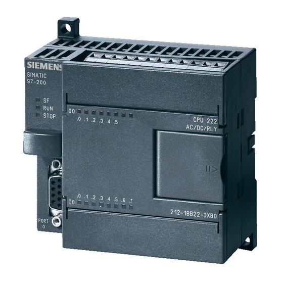
Siemens Simatic S7 Series Manuals
Manuals and User Guides for Siemens Simatic S7 Series. We have
2
Siemens Simatic S7 Series manuals available for free PDF download: System Manual, Manual
Siemens Simatic S7 Series System Manual (726 pages)
Brand:
Siemens
| Category:
Controller
| Size: 15.42 MB
Table of Contents
Preface
3
Table of Contents
5
1 Product Overview
17
S7-200 Smart Cpu
18
S7-200 SMART Expansion Modules
20
HMI Devices for S7-200 SMART
21
Communications Options
22
Programming Software
23
New Features
24
2 Getting Started
25
Connecting to the CPU
25
Configuring the CPU for Communication
26
Overview
26
Establishing the Hardware Communication Connection
27
Setting up Communication with the CPU
27
Creating the Sample Program
29
Network 1: Starting the Timer
30
Network 2: Turning the Output on
31
Network 3: Resetting the Timer
32
Setting the CPU Type and Version for Your Project
33
Saving the Sample Project
34
Downloading the Sample Program
35
Changing the Operating Mode of the CPU
36
3 Installation
37
Guidelines for Installing S7-200 SMART Devices
37
Power Budget
39
Installation and Removal Procedures
41
Mounting Dimensions for the S7-200 SMART Devices
41
Installing and Removing the CPU
42
Installing and Removing an Expansion Module
45
Installing and Removing a Signal Board or Battery Board
46
Removing and Reinstalling the Terminal Block Connector
48
Wiring Guidelines
49
4 PLC Concepts
55
Execution of the Control Logic
55
Reading the Inputs and Writing to the Outputs
57
Immediately Reading or Writing the I/O
57
Executing the User Program
58
Accessing Data
60
Accessing Memory Areas
61
Format for Real Numbers
68
Format for Strings
68
Assigning a Constant Value for Instructions
69
Addressing the Local and Expansion I/O
69
Using Pointers for Indirect Addressing
70
Pointer Examples
73
Saving and Restoring Data
75
Downloading Project Components
75
Uploading Project Components
77
Types of Storage
78
Using a Memory Card
79
Inserting a Memory Card in the CPU
81
Transferring Your Program with a Memory Card
81
Restoring Data after Power on
84
Changing the Operating Mode of the CPU
84
5 Programming Concepts
85
Guidelines for Designing a PLC System
85
Elements of the User Program
87
Creating Your User Program
90
Earlier Versions of STEP 7-Micro/Win Projects
90
Using STEP 7-Micro/Win SMART User Interface
92
Using STEP 7-Micro/Win SMART to Create Your Programs
93
Using Wizards to Help You Create Your Control Program
94
Features of the LAD Editor
95
Features of the FBD Editor
96
Features of the STL Editor
96
Data Block (DB) Editor
97
Symbol Table
100
Variable Table
104
PLC Error Reaction
109
Non-Fatal Errors and I/O Errors
110
Fatal Errors
111
Program Edit in RUN Mode
112
Features for Debugging Your Program
114
6 PLC Device Configuration
115
Configuring the Operation of the PLC System
115
System Block
115
Configuring Communication
117
Configuring the Digital Inputs
119
Configuring the Digital Outputs
121
Configuring the Retentive Ranges
122
Configuring System Security
124
Configuring the Startup Options
128
Configuring the Analog Inputs
129
Reference to the Analog Inputs Technical Specifications
131
Configuring the Analog Outputs
132
Reference to the Analog Outputs Technical Specifications
133
Configuring the RTD Analog Inputs
134
Configuring the TC Analog Inputs
139
Configuring the RS485/RS232 CM01 Communications Signal Board
143
Configuring the BA01 Battery Signal Board
144
Clearing PLC Memory
145
Creating a Reset-To-Factory-Defaults Memory Card
147
High-Speed I/O
148
7 Program Instructions
149
Bit Logic
149
Standard Inputs
149
Immediate Inputs
151
Logic Stack Overview
152
STL Logic Stack Instructions
154
Not
156
Positive and Negative Transition Detectors
157
Coils: Output and Output Immediate Instructions
158
Set, Reset, Set Immediate, and Reset Immediate Functions
159
Set and Reset Dominant Bistable
160
NOP (no Operation) Instruction
161
Bit Logic Input Examples
162
Bit Logic Output Examples
163
Clock
165
Read and Set Real-Time Clock
165
Read and Set Real-Time Clock Extended
167
Communication
170
GET and PUT (Ethernet)
170
Transmit and Receive (Freeport on RS485/RS232)
178
Get Port Address and Set Port Address (PPI Protocol on RS485/RS232)
190
Get IP Address and Set IP Address (Ethernet)
191
Compare
192
Compare Number Values
192
Compare Character Strings
196
Convert
198
Standard Conversion Instructions
198
ASCII Character Array Conversion
202
Number Value to ASCII String Conversion
208
ASCII Sub-String to Number Value Conversion
212
Encode and Decode
215
Counters
216
Counter Instructions
216
High-Speed Counter Instructions
220
Noise Reduction for High-Speed Inputs
224
High-Speed Counter Programming
226
Example Initialization Sequences for High-Speed Counters
238
Pulse Output
247
Pulse Output Instruction (PLS)
247
Pulse Train Output (PTO)
249
Pulse Width Modulation (PWM)
251
Using SM Locations to Configure and Control the PTO/PWM Operation
252
Calculating the Profile Table Values
255
Math
259
Add, Subtract, Multiply, and Divide
259
Multiply Integer to Double Integer and Divide Integer with Remainder
262
Trigonometry, Natural Logarithm/Exponential, and Square Root
264
Increment and Decrement
266
Pid
268
Using the PID Wizard
269
PID Algorithm
274
Converting and Normalizing the Loop Inputs
278
Converting the Loop Output to a Scaled Integer Value
279
Forward- or Reverse-Acting Loops
279
Interrupt
282
Interrupt Instructions
282
Interrupt Routine Overview and CPU Model Event Support
284
Interrupt Programming Guidelines
285
Types of Interrupt Events that the S7-200 SMART CPU Supports
287
Interrupt Priority, Queuing, and Example Program
288
Logical Operations
293
Invert
293
AND, OR, and Exclusive or
294
Move
296
Move Byte, Word, Double Word, or Real
296
Block Move
297
Swap Bytes
298
Move Byte Immediate (Read and Write)
299
Program Control
300
FOR-NEXT Loop
300
JMP (Jump to Label)
301
SCR (Sequence Control Relay)
303
END, STOP, and WDR (Watchdog Timer Reset)
312
GET_ERROR (Get Non-Fatal Error Code)
313
Shift and Rotate
315
Shift Register Bit
317
String
320
String (Get Length, Copy, and Concatenate)
320
Copy Substring from String
322
Find String and First Character Within String
323
Table
326
Add to Table
326
First-In-First-Out and Last-In-First-Out
328
Memory Fill
330
Table Find
331
Timer
335
Timer Instructions
335
Timer Programming Tips and Examples
337
Interval Timers
344
Subroutine
346
CALL (Subroutine) and RET (Conditional Return)
346
8 Communication
353
CPU Communication Connections
354
CPU Communication Ports
355
Hmis and Communication Drivers
355
Ethernet
357
Overview
357
TCP/IP Protocol
357
Local/Partner Connection
358
Sample Ethernet Network Configurations
358
Assigning Internet Protocol (IP) Addresses
359
Assigning IP Addresses to Programming and Network Devices
359
Configuring or Changing an IP Address for a CPU or Device in Your Project
362
Searching for Cpus and Devices on Your Ethernet Network
369
Locating the Ethernet (MAC) Address on the CPU
370
HMI-To-CPU Communication
371
Profibus
372
EM DP01 PROFIBUS DP Module
373
Distributed Peripheral (DP) Standard Communications
373
Using the EM DP01 to Connect an S7-200 SMART as a DP Device
374
Configuring the EM DP01
375
Data Consistency
376
Supported Configurations
377
Installing the EM DP01 GSD File
378
Configuring the EM DP01 I/O
379
Example of V Memory and I/O Address Area
382
User Program Considerations
384
LED Status Indicators for the EM DP01 PROFIBUS DP
386
Using Hmis and S7-Cpus with the EM DP01
387
Device Database File: GSD
388
PROFIBUS DP Communications to a CPU Example Program
392
Reference to the EM DP01 PROFIBUS DP Module Technical Specifications
394
PPI Protocol
395
Rs485
395
Baud Rate and Network Address
396
Definition of Baud Rate and Network Address
396
Setting the Baud Rate and Network Address for the S7-200 SMART CPU
397
Sample RS485 Network Configurations
399
Single-Master PPI Networks
399
Multi-Master and Multi-Slave PPI Networks
399
Building Your Network
400
General Guidelines
400
Determining the Distances, Transmission Rates, and Cable Lengths for Your Network
401
Repeaters on the Network
401
Selection of the Network Cable
402
Connector Pin Assignments
402
Biasing and Terminating the Network Cable
403
Biasing and Terminating the CM01 Signal Board
405
Using HMI Devices on Your RS485 Network
405
Freeport Mode
406
Creating User-Defined Protocols with Freeport Mode
406
Using the RS232/PPI Multi-Master Cable and Freeport Mode with RS232 Devices
409
Rs232
410
9 Libraries
411
Creating a User-Defined Library of Instructions
411
USS Library Instructions
413
USS Communication Overview
413
USS Protocol Overview
413
Requirements for Using the USS Protocol
414
Calculating the Time Required for Communicating with the Drive
415
USS Program Instructions
416
Using the USS Protocol Instructions
416
USS_INIT Instruction
417
USS_CTRL Instruction
419
Uss_Rpm_X Instruction
422
Uss_Wpm_X Instruction
425
USS Protocol Execution Error Codes
428
USS Protocol Example Program
429
Modbus Library Instructions
431
Modbus Communication Overview
431
Modbus Library Features
431
Initialization and Execution Time for Modbus Protocol
433
Modbus Addressing
434
Modbus RTU Master
436
Using the Modbus Master Instructions
436
MBUS_CTRL Instruction (Initialize Master)
437
MBUS_MSG Instruction
438
Modbus Master Execution Error Codes
442
Modbus RTU Slave
443
Using the Modbus Slave Instructions
443
MBUS_INIT Instruction (Initialize Slave)
445
MBUS_SLAVE Instruction
446
Modbus Slave Execution Error Codes
448
Modbus Master Example Program
448
Modbus Advanced User Information
450
10 Debugging and Troubleshooting
453
Debugging Your Program
453
Bookmark Functions
453
Cross Reference Table
454
Displaying Program Status
456
Displaying Status in the Program Editor
456
Configuring the STL Status Options
459
Using a Status Chart to Monitor Your Program
460
Forcing Specific Values
462
Writing and Forcing Outputs in STOP Mode
463
How to Execute a Limited Number of Scans
464
Hardware Troubleshooting Guide
465
11 PID Loops and Tuning
467
PID Loop Definition Table
468
Prerequisites
472
Auto-Hysteresis and Auto-Deviation
472
Auto-Tune Sequence
473
Exception Conditions
475
Notes Concerning PV Out-Of-Range (Result Code 3)
476
PID Tune Control Panel
476
12 Open Loop Motion Control
481
Using the PWM Output
482
Configuring the PWM Output
482
Pwmx_Run Subroutine
483
Using Motion Control
485
Maximum and Start/Stop Speeds
485
Entering the Acceleration and Deceleration Times
486
Configuring the Motion Profiles
487
Features of Motion Control
490
Programming an Axis of Motion
492
Configuring an Axis of Motion
493
Subroutines Created by the Motion Wizard for the Axis of Motion
506
Guidelines for Using the Motion Subroutines
507
Axisx_Ctrl Subroutine
507
Axisx_Man Subroutine
509
Axisx_Goto Subroutine
510
Axisx_Run Subroutine
512
Axisx_Rseek Subroutine
513
Axisx_Ldoff Subroutine
514
Axisx_Ldpos Subroutine
515
Axisx_Srate Subroutine
516
Axisx_Dis Subroutine
517
Axisx_Cfg Subroutine
518
Axisx_Cache Subroutine
519
Axisx_Rdpos Subroutine
520
Axisx_Abspos Subroutine
521
Using the Axisx_Abspos Subroutine to Read the Absolute Position from a SINAMICS Servo Drive
523
Axisx_Abspos and Axisx_Ldpos Subroutines Usage Examples
523
Interconnections
524
Commissioning
525
Control Mode
525
Setpoint Pulse Input Channel
525
Setpoint Pulse Train Input Format
525
Common Engineering Units Basis
525
Important Facts to Know
528
Axis of Motion Example Programs
529
Axis of Motion Simple Relative Move (Cut-To-Length Application) Example
529
Axis of Motion Axisx_Ctrl, Axisx_Run, Axisx_Seek, and Axisx_Man Example
531
Monitoring the Axis of Motion
535
Displaying and Controlling the Operation of the Axis of Motion
537
Displaying and Modifying the Configuration of the Axis of Motion
542
Displaying the Profile Configuration for the Axis of Motion
542
Error Codes for the Axis of Motion (WORD at SMW620, SMW670, or SMW720)
544
Error Codes for the Motion Instruction (Seven LS Bits of SMB634, SMB684, or SMB734)
545
Advanced Topics
547
Understanding the Configuration/Profile Table for the Axis of Motion
547
Special Memory (SM) Locations for the Axis of Motion
556
Understanding the RP Seek Modes of the Axis of Motion
559
Selecting the Work Zone Location to Eliminate Backlash
564
Technical Specifications
565
General Specifications
565
General Technical Specifications
565
A.1 General Specifications
565
S7-200 SMART Cpus
570
CPU ST20 and CPU SR20
570
General Specifications and Features
570
Digital Inputs and Outputs
573
CPU ST20 and CPU SR20 Wiring Diagrams
575
CPU ST30 and CPU SR30
577
General Specifications and Features
577
Digital Inputs and Outputs
580
CPU ST30 and CPU SR30 Wiring Diagrams
582
CPU ST40, CPU SR40, and CPU CR40
584
General Specifications and Features
584
Digital Inputs and Outputs
587
CPU ST40, SR40 and CR40 Wiring Diagrams
590
CPU ST60, CPU SR60, and CPU CR60
593
General Specifications and Features
593
Digital Inputs and Outputs
596
CPU ST60, SR60 and CR60 Wiring Diagrams
599
Wiring Diagrams for Sink and Source Input, and Relay Output
602
Digital Inputs and Outputs Expansion Modules (Ems)
603
EM DE08 Digital Input Specifications
603
EM DT08 and EM DR08 Digital Output Specifications
604
EM DT16, EM DR16, EM DT32, and EM DR32 Digital Input/Output Specifications
607
Analog Inputs and Outputs Expansion Modules (Ems)
613
EM AE04 and EM AE08 Analog Input Specifications
613
EM AQ02 and EM AQ04 Analog Output Module Specifications
616
EM AM03 and EM AM06 Analog Input/Output Module Specifications
618
Step Response of the Analog Inputs
623
Sample Time and Update Times for the Analog Inputs
623
Measurement Ranges of the Analog Inputs for Voltage and Current (SB and EM)
624
Measurement Ranges of the Analog Outputs for Voltage and Current (SB and EM)
625
Thermocouple and RTD Expansion Modules (Ems)
626
Thermocouple Expansion Modules (Ems)
626
EM AT04 Thermocouple Specifications
626
RTD Expansion Modules (Ems)
632
Digital Signal Boards
637
SB DT04 Digital Input/Output Specifications
637
Analog Signal Boards
640
SB AE01 Analog Input Specifications
640
SB AQ01 Analog Output Specifications
642
RS485/RS232 Signal Boards
644
SB RS485/RS232 Specifications
644
Battery Board Signal Boards (Sbs)
646
SB BA01 Battery Board
646
EM DP01 PROFIBUS DP Module
648
S7-200 SMART Cpus that Support the EM DP01 PROFIBUS DP Module
649
Connector Pin Assignments for EM DP01
650
EM DP01 PROFIBUS DP Module Wiring Diagram
651
Calculating a Power Budget
653
Power Budget
653
B.1 Power Budget
653
Calculating a Sample Power Requirement
655
Calculating Your Power Requirement
656
Error Codes
657
PLC Non-Fatal Error Codes
657
PLC Non-Fatal Error SM Flags
660
PLC Fatal Error Codes
661
Timestamp Mismatch
663
C.4 Timestamp Mismatch
663
Special Memory (SM) and System Symbol Names
665
SM (Special Memory) Overview
665
SMB0: System Status
667
SMB1: Instruction Execution Status
668
SMB2: Freeport Receive Character
669
SMB3: Freeport Character Error
669
SMB4: Interrupt Queue Overflow, Run-Time Program Error, Interrupts Enabled, Freeport Transmitter Idle, and Value Forced
670
SMB5: I/O Error Status
670
SMB6-SMB7: CPU ID, Error Status, and Digital I/O Points
671
SMB8-SMB19: I/O Module ID and Errors
672
SMW22-SMW26: Scan Times
673
SMB28-SMB29: Signal Board ID and Errors
673
SMB30: (Port 0) and SMB130: (Port 1)
674
SMB34-SMB35: Time Intervals for Timed Interrupts
674
SMB36-45 (HSC0), SMB46-55 (HSC1), SMB56-65 (HSC2), SMB136-145 (HSC3): High-Speed Counters
675
SMB66-SMB85, SMB166-SMB169, SMB176-SMB179, and SMB566-SMB579: PTO0, PWM0, PTO1, PWM1, PTO2, and PWM2 High-Speed Outputs
678
SMB86-SMB94 and SMB186-SMB194: Receive Message Control
681
SMW98: I/O Expansion Bus Communication Errors
683
SMW100-SMW114 System Alarms
684
SMB130: Freeport Control for Port 1 (See SMB30)
685
SMB136-SMB145: HSC3 High-Speed Counter
685
SMB186-SMB194: Receive Message Control (See SMB86-SMB94)
685
SMB480-SMB515: Data Log Status
685
SMB600-SMB749: Axis (0, 1, and 2) Open Loop Motion Control
686
SMB650-SMB699: Axis 1 Open Loop Motion Control (See SMB600-SMB740)
687
SMB700-SMB749: Axis 2 Open Loop Motion Control (See SMB600-SMB740)
687
SMB1000-SMB1049: CPU Hardware/Firmware ID
688
SMB1050-SMB1099: SB (Signal Board) Hardware/Firmware ID
688
SMB1100-SMB1399: EM (Expansion Module) Hardware/Firmware ID
689
SMB1400-SMB1699: EM (Expansion Module) Module-Specific Data
691
References
693
Often-Used Special Memory Bits
693
E.1 Often-Used Special Memory Bits
693
Interrupt Events in Priority Order
694
High-Speed Counter Summary
695
Instructions
696
E.4 Instructions
696
Memory Ranges and Features
703
Ordering Information
705
CPU Modules
705
Expansion Modules (Ems) and Signal Boards (Sbs)
705
F.1 CPU Modules
705
Programming Software
706
Communication
706
Spare Parts and Other Hardware
706
F.3 Programming Software
706
Human Machine Interface Devices
708
Index
709
Advertisement
Siemens Simatic S7 Series Manual (75 pages)
Brand:
Siemens
| Category:
Controller
| Size: 3.57 MB
Table of Contents
Table of Contents
2
Introduction
3
Plcs
5
Number.systems
9
Terminology
13
Basic.requirements
19
S7-200.Micro.plcs
21
Programming.a.plc
34
Discrete.inputs/Outputs
42
Analog.inputs.and.outputs
49
Timers
52
Counters
59
High-Speed.instructions
62
Specialized.expansion.modules
66
Review.answers
73
Final.exam
75
Advertisement
Related Products
Siemens SIMATIC 500
Siemens SIMATIC EM 300
Siemens SIMATIC PN/BACnet LINK
Siemens SIMATIC NET SCALANCE WLC711
Siemens SIMATIC SIS compact
Siemens SIMATIC S7-1200 TCSB V3
Siemens SIMATIC S5 Series
Siemens SIMATIC PCS 7 CPU 410-5H
Siemens SIMATRIX
Siemens Simantic S7-1500
Siemens Categories
Industrial Equipment
Controller
Control Unit
Oven
Washer
More Siemens Manuals
Login
Sign In
OR
Sign in with Facebook
Sign in with Google
Upload manual
Upload from disk
Upload from URL