Sign In
Upload
Manuals
Brands
Siemens Manuals
Engine
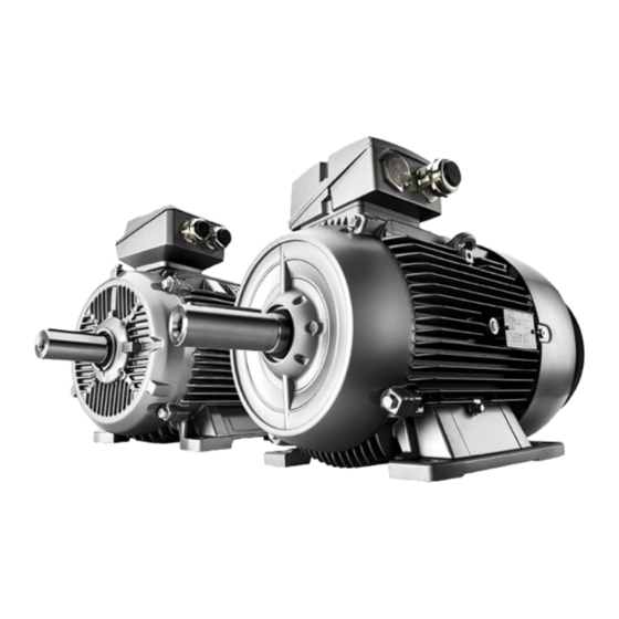
SIMOTICS XP Eagle Line 1MB1.33
Siemens SIMOTICS XP Eagle Line 1MB1.33 Manuals
Manuals and User Guides for Siemens SIMOTICS XP Eagle Line 1MB1.33. We have
1
Siemens SIMOTICS XP Eagle Line 1MB1.33 manual available for free PDF download: Operating Instructions Manual
Siemens SIMOTICS XP Eagle Line 1MB1.33 Operating Instructions Manual (176 pages)
Low-voltage motors, Shaft heights 71...315
Brand:
Siemens
| Category:
Engine
| Size: 5.96 MB
Table of Contents
Table of Contents
5
Introduction
11
About SIMOTICS
11
About this Manual
11
Content
11
Target Group
12
Avoiding Dangers
12
Standard Scope
13
Websites of Third-Party Companies
13
SIMOTICS Documentation
13
Service and Support
14
Siemens Industry Online Support on the Web
14
Siemens Industry Online Support on the Road
15
Feedback on the Technical Documentation
16
Mysupport Documentation
16
Technical Support
17
Training
18
Spare Parts Services
18
Important Product Information
18
Safety Information
19
Information for those Responsible for the Plant/System
19
The 5 Safety Rules
19
Qualified Personnel
20
Safe Handling
20
Use in Hazardous Areas
22
Explosion Hazard from Hybrid Mixtures
23
Electrostatic Sensitive Devices
24
Electromagnetic Compatibility
25
Interference Immunity
25
Influence on the Line Power Supply through a Strongly Irregular Torque
26
Interference Voltages When Operating the Converter
26
Special Designs and Construction Versions
26
Certificate with Special Conditions
26
Description
29
Area of Application
29
Rating Plates
31
Installation
32
Regulations
33
Cooling and Ventilation
35
Machines with a Fan
35
Machines Without a Fan (Optional)
35
Bearings
36
Axial and Radial Forces
36
Balancing
36
Types of Construction/Method of Installation
37
Degree of Protection
39
Degree of Protection for Explosion Protected Machines
39
Environmental Conditions
40
Optional Built-On and Built-In Accessories
40
Marking
42
Terminal Box
45
Paint Finish
45
Preparing for Use
47
Safety-Related Aspects to Consider When Configuring the Plant
47
Observing the Operating Mode
47
Machines Without Final Paint Coating
47
Delivery
48
Transport and Storage
48
Safety Instructions for Transport
48
Storage
51
Temperature Limits During Storage
52
Securing the Rotor
53
Commissioning after Storage
55
Insulation Resistance and Polarization Index
55
Lubricating the Rolling Bearings
55
Regreasing Rolling Bearings after Storage Periods of up to Two Years
55
Releasing the Rotor Shipping Brace before Commissioning
55
Ensure Adequate Cooling
56
Thermal Protection
57
Interlock Circuit for Anti-Condensation Heating
59
Noise Emission
59
Voltage and Frequency Fluctuations During Line Operation
59
Rotational Speed Limit Values
60
System-Inherent Frequencies
60
Electromagnetic Compatibility
60
Converter Operation
61
Parameterizing the Converter
61
Converter Input Voltage
62
Reducing Bearing Currents
62
Insulated Bearings for Converter Operation
63
Tandem Operation
65
Speed Limits for Converter Operation
65
Assembly
67
Safety Instructions for Installation
67
Preparing for Installation
68
Requirements for Installation
68
Insulation Resistance
69
Insulation Resistance and Polarization Index
69
Checking the Insulation Resistance and Polarization Index of the Winding
70
Mounting and Installed the Machine
73
Preparing the Assembly Area
73
Lift the Machine to Where It will be Mounted and Position It
73
Machines with Type of Construction IM B15, IM B9, IM V8 and IM V9
74
Foot Mounting
74
Alignment and Fastening
75
Repainting/Touching up the Paint Finish of Explosion-Protected Machines
75
Measures for Alignment and Mounting
76
Flatness of the Supporting Surfaces for Conventional Motors
76
Machine Frame Mounting Feet (Special Design)
77
Installing the Machine
77
Preconditions for Smooth, Vibration-Free Operation
77
Aligning the Machine to the Driven Machine and Mounting
77
Type of Construction Without Flange
77
Horizontal Types of Construction with Mounting Feet
77
Horizontal Types of Construction with Flange
78
Vertical Types of Construction with Flange
79
Removing the Rotor Shipping Brace
79
Recommended Alignment Accuracy
80
Mounting the Drive Output Elements
80
Electrical Connection
85
Connecting the Machine
86
Safe Connection
86
Selecting Cables
87
Thermal Protection
87
Terminal Box
88
Circuit Diagram Inside the Terminal Box Cover
88
Direction of Rotation
88
Terminal Marking
89
Additional Bores in the Terminal Box
89
Cable Entry
89
Protruding Connection Cables
90
Connecting Protruding Cables
91
Thread Sizes in the Terminal Box
91
Internal Equipotential Bonding
91
Cable Glands
92
Mounting Position of Sheet Metal Nuts in Screw-Type Connections
92
Tightening Torques
93
Connecting the Grounding Conductor
93
Minimum Surface Area of Grounding Conductor
93
Grounding Connection Type
94
Temperature Sensor/Anti-Condensation Heating Connection
95
Connecting Optional Integrated Devices and Equipment
95
Conductor Connection
96
Connection With/Without Cable Lugs
99
Cable Ends with Wire End Sleeves
99
Connecting Aluminum Conductors
100
Minimum Air Clearances
100
Connecting the Converter
101
Final Checks
102
Commissioning
105
Measures before Commissioning
105
Insulation Resistance and Polarization Index
107
Checking the Machine Cooling
107
Commissioning the Separately Driven Fan
108
Further Documents
109
Setpoint Values for Monitoring the Bearing Temperature
109
Switching on
109
Test Run
111
Operation
113
Safety Instructions for Operation
113
Safety Instructions Relating to Ventilation and Cooling
117
Forced Ventilation (Optional): Cooling Method IC 416 in Accordance with
117
Iec 60034-6
117
Switching on with the Anti-Condensation Heating Active
118
Switching on the Machine
119
Switch off the Separately Driven Fan
119
Switching on Again after an EMERGENCY off
119
Stoppages
119
Avoidance of Damage to Rolling Bearings During Stoppages
121
Decommissioning the Machine
121
Re-Commissioning the Machine
121
Faults
122
Inspections in the Event of Faults
122
Electrical Faults
122
Mechanical Faults
123
Rolling Bearing Faults
124
Faults at the External Fan
124
Deactivating
124
Maintenance
125
General
125
Inspection and Maintenance
126
Safety Instructions for Inspection and Maintenance
126
Inspections in the Event of Faults
128
First Inspection after Installation or Repair
129
General Inspection
130
Assessing the Rolling Bearings
130
Mechanical Explosion Protection for Rolling Bearings
131
Maintenance Intervals
131
Re-Greasing
132
Cleaning
133
Risk of Explosion Due to Damaged Seals
134
Drain Condensate
134
Insulation Resistance and Polarization Index
135
Maintaining the External Fan (Forced Ventilation)
135
Repainting
136
Corrective Maintenance
137
Machines with a Certificate Extended with an "X
138
Anti-Condensation Heating
138
Fundamentals
139
Rolling Bearings
139
Replacing Bearings in Explosion-Proof Machines
141
Fitting Bearings
141
Explosion Hazard Due to Overheating of the Rolling Bearings
143
Shaft Sealing, Mounting Dimensions and Alignment
143
Fan
144
Mounting Fans
145
Cable Entries, Sealing Plugs and Thread Adapters
145
Tightening Torques
145
Screw Lock Washers
145
Links
145
Reassembly: Miscellaneous Information
146
Optional Add-On Units
146
O-Ring Seal
146
Spare Parts
147
Parts Order
147
Purchasing Commercially Available Spare Parts
148
Determining the Spare Parts Via the Internet
148
Replacing Rolling Bearings
148
Rolling Bearings
148
Anti-Condensation Heating
149
Groups of Parts
149
Ordering Example
150
Machine Parts
151
Part Lists
151
Standardized Parts
153
Exploded Drawings
154
1MB1 Shaft Heights 71
154
1MB1 Shaft Heights 100
155
1MB1 Shaft Heights 225
156
Terminal Box 1MB1 Shaft Heights 71
157
Terminal Box 1MB1 Shaft Heights 200
158
Terminal Box 1MB1 Shaft Heights 250
160
Terminal Box 1MB1 Shaft Height 315 Cast Iron
162
Disposal
165
Introduction
165
Rohs - Restricting the Use of Certain Hazardous Substances
165
Note Regarding Article 33 of the REACH Regulation
165
Preparing for Disassembly
166
Dismantling the Machine
166
Disposal of Components
166
Technical Data
169
Tightening Torques
169
Tightening Torques for Screw and Bolt Connections
169
Stud-Type Bushings
170
Terminal Boxes, End Shields, Grounding Conductors, Sheet Metal Fan Covers
170
Terminal Board and Grounding
170
Tightening Torques of Additional Connecting Terminals
171
Quality Documents
173
Quality Documents SIMOTICS in SIOS
173
Advertisement
Advertisement
Related Products
Siemens SIMOTICS XP 1MB5 SH400
Siemens SIMOTICS XP 1MB5 SH450
Siemens SIMOTICS 1LE
Siemens SIMOTICS-T 1FW68
Siemens 1LP6
Siemens 1PH4 103
Siemens 1PH4 133
Siemens 1PM103
Siemens 1FK703 Series
Siemens 1FS6134
Siemens Categories
Industrial Equipment
Controller
Control Unit
Oven
Washer
More Siemens Manuals
Login
Sign In
OR
Sign in with Facebook
Sign in with Google
Upload manual
Upload from disk
Upload from URL