Sign In
Upload
Manuals
Brands
Siemens Manuals
Engine
SINAMICS S 1PH7
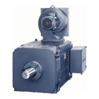
User Manuals: Siemens SINAMICS S 1PH7 Induction Motor
Manuals and User Guides for Siemens SINAMICS S 1PH7 Induction Motor. We have
1
Siemens SINAMICS S 1PH7 Induction Motor manual available for free PDF download: Configuration Manual
Siemens SINAMICS S 1PH7 Configuration Manual (245 pages)
Induction Motors for Machine Tools
Brand:
Siemens
| Category:
Engine
| Size: 6.81 MB
Table of Contents
Contents
3
Proper Use of Siemens Products
4
Qualified Personnel
4
Warning Notice System
4
Standard Scope
5
Preface
5
Technical Support
6
Danger and Warning Information
7
Information Regarding Third-Party Products
10
Environmental Compatibility
10
Residual Risks of Power Drive Systems
11
Table of Contents
13
Target Group
5
1 Motor Description
17
Properties
17
Benefits
17
Area of Application
18
Torque Overview
18
Technical Features
19
Options
21
Codes and Option Description
21
Selection and Ordering Data
22
Rating Plate Data
36
Schematic Layout of Rating Plate
36
Elements on the Rating Plate
37
2 Configuration
39
Configuring Software
39
SIZER Engineering Tool
39
Minimum System Requirements
40
Order Number for SIZER
40
STARTER Drive/Commissioning Software
41
Sinucom Commissioning Tool
41
SINAMICS Procedure When Engineering
42
Motion Control
42
General Configuring Procedure
42
Configuring Procedure
42
Connection System
42
Selecting and Dimensioning Induction Motors
43
Clarification of the Type of Drive
43
Defining the Supplementary Conditions and Integration into an Automation System
43
Selecting Induction Motors
44
Motor Operates Continuously
44
Motor Operates with a Periodic Duty Cycle
45
Periodic Duty Cycle (Example)
45
Motor Selection
46
Selection of Motor Modules
46
A High Field Weakening Range Is Required
46
Motor Selection Based on Power-Speed and Torque-Speed Diagrams
47
3 Mechanical Properties of the Motors
49
Cooling
49
Ambient/Cooling Medium Temperature
49
Factors for Reducing the Torque/Power Acc. to en 60034-6
49
Fan Mounting
50
Minimum Clearances
50
Air Flow Rate, Air Flow Direction and Air Discharge
50
Cleaning the Cooling Air Passages
51
Motors with Pipe Connection
51
Degree of Protection Acc. to en 60034-5
52
Degree of Protection Designation
52
Bearing Version
53
Drive Output Types and Bearing Versions
53
Drive Output Type with the Appropriate Bearing Design
53
Output Type, Bearing Version and Maximum Speed
54
Bearing Lifetime
55
Lifetime Lubrication (Without Re-Lubricating)
55
Bearing Change Interval
55
Recommended Bearing Change Intervals (Standard Bearing Design)
56
Regreasing Intervals
57
Radial and Axial Forces
59
Radial Force (Cantilever Force)
59
Explanation of the Formula Abbreviations
60
Radial Force Diagrams
61
SH 100, Permissible Radial Forces for a Standard Bearing Design
61
SH 100, Permissible Radial Forces for Increased Max. Speed
62
SH 132, Permissible Radial Forces for a Standard Bearing Design
63
SH 132, Permissible Radial Forces for Increased Max. Speed
64
SH 160, Permissible Radial Forces for a Standard Bearing Design
65
SH 160, Permissible Radial Forces for Increased Max. Speed
66
SH 180, Permissible Radial Forces for a Coupling Output
67
SH 180, Permissible Radial Forces for Belt Couplings
68
SH 180, Permissible Increased Radial Forces for Belt Couplings
69
SH 225, Permissible Radial Forces for a Coupling Output
70
SH 225, Permissible Radial Forces for Belt Couplings
71
SH 225, Permissible Increased Radial Forces for Belt Couplings
72
Axial Force
73
Calculating the Permissible Axial Force
73
Axial Force Diagrams
74
SH 100, Permissible Axial Force
75
SH 132, Permissible Axial Force
75
Axial Force Diagram, SH 100
75
Axial Force Diagram, SH 132
75
SH 160, Permissible Axial Force
76
SH 100, Permissible Axial Force for the Option, Increased Max. Speed
77
SH 132, Permissible Axial Force for the Option, Increased Max. Speed
77
SH 160, Permissible Axial Force for the Option, Increased Max. Speed
78
Cantilever Force Diagram, SH 160 (Increased Max. Speed)
78
Shaft End and Balancing
79
Radial Eccentricity, Concentricity and Axial Eccentricity
80
Balancing Process
81
Checking the Concentricity and Axial Eccentricity
81
Special Requirements
82
Vibration Severity Level
83
Vibration Severity Limit Values for Induction Motors SH 100 to 132
83
Paint Finish
84
Vibration Severity Limit Values for Induction Motors SH 160 to 225
84
4 Technical Data and Characteristics
85
Mode of Operation and Characteristics
85
Power Characteristics, Limits and Curves; Torque-Speed Diagram
85
Power Rating Data for Duty Types S1 and S6
86
Output Voltages
86
Speed Limit
86
Offset of the Voltage Limit Characteristic
87
Calculating the New Voltage Limiting Characteristic
87
An Example of the Offset in the Voltage Limiting Characteristic
88
P/N and M/N Characteristics
89
Explanation of the Abbreviations Used
89
Dimension Drawings
172
Cad Creator
172
How Up-To-Date Are the Dimension Drawings
173
Dimension Drawings IM B3
174
1PH7, Type of Construction IM B3, Forced Ventilation
174
Dimension Drawings IM B5
180
Dimension Drawings IM B35
183
1PH7 Motors with DRIVE-Cliq, Deviating and Additional Dimensions
188
5 Motor Components (Options)
189
Thermal Motor Protection
189
Encoder (Option)
190
Encoder Types for Motors Without DRIVE-Cliq
190
Encoder Types for Motors with DRIVE-Cliq
190
Incremental Encoder Sin/Cos 1Vpp
191
Properties and Technical Data
191
Signal Sequence and Assignment for a Positive Direction of Rotation
191
Absolute Encoder (Endat)
192
Radial Sealing Ring
193
Degree of Protection
193
Gearbox
194
Overview
194
Gearbox Properties
195
Motor Without Selector Gearbox
195
Vibration Levels
196
Information Regarding Spindle Applications
196
Gearbox Design
197
Belt Pulley
197
Gearbox Design for 1PH7, SH 100 to 160
197
Technical Data
198
Technical Data for Gearbox
198
Electrical Connection
199
Electrical Connection with Solenoid
199
Electrical Connection for the Motorized Selector Unit
200
Explanation of the Connections
200
Gearbox Stage Selection
201
Function Sequence When Changing the Gearbox Stage
201
Control Sequence When Selecting the Gearbox Stage
202
Lubrication
202
Splash Lubrication
202
Circulating Oil Lubrication
202
Flange Dimensions
203
Flange Dimensions for Motors
203
Connections, Circulating Oil Lubrication, Frame Size 100
204
Selector Gearbox with Selector Unit for Frame Size 100
204
Connections, Circulating Oil Lubrication, Frame Sizes 132 and 160
205
Gearbox Dimensions
206
Motor and Gearbox Dimensions
206
Two-Stage Selector Gearbox
207
Permissible Dimension Deviations
209
6 Connection System
211
SINAMICS Drive I/O
211
Power Connection
212
Terminal Box Connection
212
Power Cable
212
Assignment, Terminal Boxes and Max. Cross-Sections
213
Current-Carrying Capacity for Power and Signal Cables
214
Cable Cross Section and Current-Carrying Capacity
214
Derating Factors for Power and Signal Cables
214
Cable Outlet at NDE (Integrated Terminal Box)
215
Cable Outlet up to SH 225
215
Connecting-Up Information
216
Internal Potential Bonding
216
Motor and Connecting Cables
216
After Connecting-Up, the Following Points Should be Checked/Tested
217
Connecting the Ground Conductor
217
Screw-In Depth and Tightening Torque
217
Supply Data for Separately-Driven Fans
218
Recommended Connection
218
Signal Connection
219
Encoder Connection on Motors with DRIVE-Cliq
219
Cables on Motors with DRIVE-Cliq
220
Encoder Connection for Motors Without DRIVE-Cliq
220
Cables for Motors Without DRIVE-Cliq
221
Pre-Fabricated Cable for Incremental Encoder
221
Pre-Fabricated Cable for Absolute Encoder
221
7 Information for Using the Motors
223
Transportation/Storage before Use
223
Ambient Conditions
223
Factors to Reduce the Torque/Power (De-Rating)
223
Routing Cables in a Damp Environment
224
Principle of Cable Routing in a Wet/Moist Environment
224
Mounting Position/Types of Construction
225
Designation of Types of Construction (Acc. to IEC 60034-7)
225
Mounting
226
Flange Mounting
227
Flange Mounting with Threaded Studs and Nuts
227
Mounting and Mounting Instructions
228
Limiting the Maximum Speed
228
Natural Frequency When Mounted
230
Vibration Stressing
231
Vibration Values for SH 100 to 160
231
Vibration Values for SH 180 to 225
231
Max. Permissible Radial and Axial Vibration Values
231
Misalignment
232
Flywheels
232
Insulated Bearings (NDE) (Option L27)
233
Relevant, Additional Bearing Currents
233
Factors that Influence Bearing Currents
233
Application for Option L27
233
Motor Grounding
234
Bearing Current Due to Grounding Situation (= Rotor Ground Current)
234
Drive End
235
A.1 Description of Terms
235
Modes
236
Nde
236
Rated Frequency
236
Rated Power
236
S1 Duty (Continuous Operation)
237
S6 Duty (Intermittent Operation)
237
Overview of Publications of Planning Manuals
238
A.2 References
238
A.3 Suggestions/Corrections
239
A Appendix
241
Index
241
Advertisement
Advertisement
Related Products
Siemens SIMOTICS S-1FK7 G2
Siemens SIMOTICS S-1FT7 G2
Siemens SIMOTICS S-1FG1
Siemens SIMOTICS S-1FK7 DYA Generation 2
Siemens SINAMICS S120 1PM6
Siemens SINAMICS S120 1PM4
Siemens SIMOTICS S-1FK7
Siemens SIMOTICS S-1FT2
Siemens SIMOTICS S-1FT7
Siemens SIMOTICS DP
Siemens Categories
Industrial Equipment
Controller
Control Unit
Oven
Washer
More Siemens Manuals
Login
Sign In
OR
Sign in with Facebook
Sign in with Google
Upload manual
Upload from disk
Upload from URL