Sign In
Upload
Manuals
Brands
Siemens Manuals
Inverter
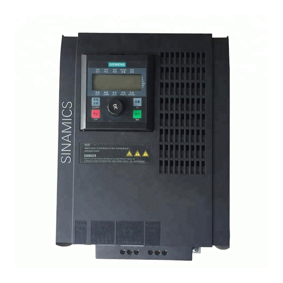
SINAMICS V10
Siemens SINAMICS V10 AC Inverter Manuals
Manuals and User Guides for Siemens SINAMICS V10 AC Inverter. We have
1
Siemens SINAMICS V10 AC Inverter manual available for free PDF download: Operating Instructions Manual
Siemens SINAMICS V10 Operating Instructions Manual (125 pages)
Brand:
Siemens
| Category:
Inverter
| Size: 15.93 MB
Table of Contents
Proper Use of Siemens Products
2
Warning Notice System
2
Table of Contents
3
1 Introduction
5
Installation
5
2 Safety Notes
7
Troubleshooting
10
3 Description
13
Overview
13
Features
14
Main Characteristics
14
Performance Characteristics
14
Protection Characteristics
14
4 Identification
15
Scope of Delivery
15
Inverter MLFB (Order Number) Explanation
16
Inverter Rating Plate
16
Rating Plate on the Rear of the Operator Panel
17
The Operator Panel Rating Plate
17
Technical Data
18
Spare Parts
19
Mechanical Installation
21
Mounting Orientation and Clearance
21
Allowed Mounting Angle between Inverter and the Horizon
22
Inverter Mounting Clearance
22
Mounting Clearance
22
Requirements for Inverter Mounting Clearance
22
Mounting Dimensions (Outline Dimensions + Drill Patterns)
23
Mounting Torque Requirements
23
Wall Mounting
23
Mounting Sequence
24
Mounting the Operator Panel to Cabinet Door
25
Push-Through Mounting
25
What Does "Push-Through Mounting" Mean?
25
Outline Dimensions of SINAMICS V10
26
Drill Patterns and Cut-Out Dimensions
27
Outline Dimensions of Optional Mounting Kits
27
Mounting Dimensions for Door-Mounted Operator Panel
31
Torques for Fixing the Operator Panel to Cabinet Door
31
Electrical Installation
33
Interface Definition
33
PE Terminal Layout
33
Layout of Interfaces Other than PE Terminals
34
Conductor Cross-Sections of Mains Input Cable/ Motor Output Cable
35
Interfaces between Inverter Body Unit and the Remote Operator Panel
35
Conductor Cross-Sections of the DI/DO, AI/AO Terminal Connecting Cable
36
Connecting Power Supply to the Motor
37
Power and Motor Connections
37
Types of SIEMENS Line Fuses (Recommended)
37
6 Commissioning
39
Typical Connection Modes
39
Typical Connection Mode 1 (C01) - Out-Of-Box Application
41
Typical Connection Mode 1 (C01)
41
Typical Connection Mode 2 (C02)
42
Typical Connection Mode 3 (C03)
43
Typical Connection Mode 4 (C04)
45
Typical Connection Mode 5 (C05)
46
Typical Connection Mode 6 (C06)
48
Typical Connection Mode 7 (C07)
49
Typical Connection Mode 8 (C08)
51
Typical Connection Mode 9 (C09)
52
Typical Connection Mode 10 (C10)
53
Typical Connection Mode 11 (C11)
55
Application Macros
56
Descriptions to Application Macro
56
Parameters Related to Application Macros
56
Operator Panel Overview
58
Overview of the Operator Panel
58
Function Overview of Operator Panel
59
Various Data Displays
60
Binary Parameter Display
61
Displays During Inverter Initialization Stage
62
Quick Commissioning
63
Motor Data
64
Inverter Status Display
65
Frequency Setpoint and Actual Value Changeover
65
Frequency Status Changeover (Example)
65
Overview of Various Operation Modes
66
Operation Mode ① - Quick Motor Data Setting
66
Parameter Setting in "Quick Motor Data Setting" Mode
67
Button/Keys Inactive in this Mode
67
Operation Mode ② - Connection Macro Selection
67
Connection Macros Available for Setting in this Mode
68
Connection Macro Setting in "Connection Macro Selection" Mode
68
Application Macros Available for Setting in this Mode
69
Application Macro Setting in "Application Macro Selection" Mode
69
Operation Mode ③ - Application Macro Selection
69
Parameters Available for Setting in this Mode
70
Operation Mode ④ - Common Application Macro Specific Parameter Setting
70
Operation Mode ⑤ - Access All the Parameters
71
Factory Reset
72
Cloning Parameters with the Operator Panel
73
7 Parameter List
75
Parameter Groups
75
Inverter Status Specific Parameters
75
Motor Data (for Quick Commissioning)
75
Digital I/O Specific Parameters
76
Analog I/O Specific Parameters
76
Frequency Reference Specific Parameters
76
Control Parameters
77
Protection Specific Parameters
77
Notes on the off Functions
78
Other Parameters
78
Selection of Frequency Setpoint
92
Disabling an Additional Setpoint
92
Fixed Frequency Selection
93
Fixed Frequency
93
Setpoint Memory of the MOP
94
Setpoint of the MOP
94
JOG Frequency Right
94
Skip Frequency
95
Skip Frequency Bandwidth
95
Inhibit Negative Frequency Setpoint
95
Selection of the ON/OFF1 Command Source
95
Selection of the OFF2 Command Source
96
Inhibiting Negative Set Points of MOP
96
CO: Frequency Setpoint before RFG
96
Ramp-Up Time
96
Flying Start
97
Automatic Restart
98
Holding Brake Enable
98
Holding Brake Release Delay
99
Holding Time after Ramp down
99
BI: Enable DC Braking
99
Duration of DC Braking
99
Compound Braking Current
100
Configuration of VDC Controller
100
Dynamic Factor of VDC-Max
101
Control Mode
101
Continuous Boost
101
Starting Boost
101
Reference Frequency
102
Ctrlwrd1 from Operator Panel
102
Warning Number
102
Enable PI Controller
103
Setpoint Memory of PI-MOP
103
Setpoint of PI
103
PI Scaled Feedback
103
PI Error
104
PI Proportion Gain
104
PI Integral Time
104
PI Output Upper Limit
104
Connection Macros Dependent Default Settings
105
8 Troubleshooting
107
Acknowledging and Clearing Fault(S)
107
Acknowledging and Clearing F0003 (Example)
108
Fault List
109
Alarm List
112
9 Technical Data
115
Technical Specifications - SINAMICS V10 Inverter
115
Replacing the Fans
119
Removing the Fans from Frame Size B
119
Removing the Fans from Frame Size C
120
Removing the Fans from Frame Size D
121
Index
123
Advertisement
Advertisement
Related Products
Siemens SINAMICS V20 Inverter
Siemens SINAMICS G120C
Siemens SINAMICS G110M
Siemens SINAMICS G180
Siemens SINAMICS Series
Siemens Sinamics ET 200pro FC-2
Siemens HIPATH V1.2.33
Siemens SIMATIC WinCC V11
Siemens Startdrive V12 SP1
Siemens TIA Portal V14
Siemens Categories
Industrial Equipment
Controller
Control Unit
Oven
Washer
More Siemens Manuals
Login
Sign In
OR
Sign in with Facebook
Sign in with Google
Upload manual
Upload from disk
Upload from URL