Sign In
Upload
Manuals
Brands
Siemens Manuals
Control Systems
SIPLUS HCS Series
Siemens SIPLUS HCS Series Control System Manuals
Manuals and User Guides for Siemens SIPLUS HCS Series Control System. We have
2
Siemens SIPLUS HCS Series Control System manuals available for free PDF download: Operating Instructions Manual
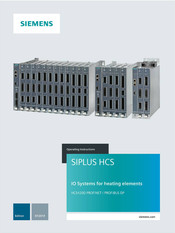
Siemens SIPLUS HCS Series Operating Instructions Manual (268 pages)
IO systems for heating elements. Heating control system
Brand:
Siemens
| Category:
Control Systems
| Size: 4.66 MB
Table of Contents
Table of Contents
5
1 Introduction
11
2 Security Information
15
Safety Information
15
Security Information
17
3 System Overview
19
Area of Application
19
Features
20
Combination Mode
23
System Configuration
24
Central Interface Module (CIM)
25
Function and Design
25
Power Output Module (POM)
28
Pom4220
28
Pom4320
31
I/O Modules
32
Pm4000 DI/Do
32
Pm4000 U/I
33
PM4000 Temperature
34
4 Application Planning
35
Shipping
35
Storage
35
Scope of Delivery
36
Installation Location
37
General Requirements for the Location of Use
37
Double Frame Construction
42
Combined Mode Configuration
44
Power Ratings
45
POM4220 Power Rating
45
POM4320 Power Rating
52
5 Installation/Mounting
55
Requirements
55
Mounting the Rack
55
Mounting the Fan Module
58
Installing the Central Interface Module (CIM)
59
Installing the I/O Module (PM)
60
Mounting a POM4220 Power Output Module
61
Mounting and Dismantling CIM4210C PROFINET
62
Mounting the Blanking Covers
63
Double Frame Setup
63
Mounting a POM4320 Power Output Module
65
Busbar Mounting
65
Preparations
65
Adjusting the Busbar Adapter
66
Mounting the POM (Busbar Adapter)
68
Panel Mounting
69
POM Mounting (Panel Mounting)
69
6 Connecting
71
Safety Information and Guidelines
71
Connecting the Protective Conductor
73
Combined Mode with POM4320 - Connecting System Interfaces
76
Connecting the PROFINET/PROFIBUS Fieldbus
78
Connect 24 V DC Power Supply
79
Connecting the Heating Elements and Three-Phase Line Supply
81
POM4220 Lowend Block Diagram
88
Block Diagram POM4220 Midrange Phase Angle Control and POM4220 Flexible
89
POM4220 Highend Block Diagram
90
Block Diagram POM4320
95
Connecting I/O Modules
96
Pm4000 DI/Do
96
Pm4000 U/I
98
PM4000 Temperature
100
7 Commissioning
103
Requirements
103
Insulation Test
104
8 Configuration
105
Integrating the HCS4200 Components into the PROFINET Configuration
105
Integrating the HCS4200 Components into the PROFIBUS Configuration
106
Device Configuration and Configuration Parameters in the TIA Portal
107
Device Configuration PROFINET HCS4200
107
Device Configuration PROFINET HCS4200 Combination Mode
108
PROFIBUS Device Configuration
109
Configuration Parameters
110
Configuration Parameters for CIM and POM
110
Configuration Parameters for I/O Modules
114
Software Tools for Commissioning Support
116
Overview of Tools for Commissioning Support
116
Configuration Control (Option Handling)
117
Configuration Control
117
Configuring
119
Controller
119
Slot Assignment
119
Control Data Record
120
Feedback Data Record
121
Transferring Control Data Record in the Startup Program of the CPU
123
Behavior During Operation
125
Examples of Configuration Control
126
Station Master HCS4200
126
Station Master HCS4200 Combined Mode
130
9 Functions
133
Overview of Functions
133
Status and Actual Displays
134
Power Output Control
134
Half-Wave Control
134
Phase Angle Control
136
Soft Starting Function
137
Switch on Heating
139
Soft Start During Heater Operation
139
Channel Control Via Setpoints
139
Channel Control Via Fields
140
Line Voltage Compensation
141
Power Control
142
Behavior of the Power Outputs
143
Digital Inputs/Outputs
144
Recording of Analog Measured Line Values
145
Recording of Analog Measured Line Values with PM4000 U/I
145
Recording of Analog Measured Line Values with POM4220 Highend
146
Recording of Analog Measured Values
147
Monitoring Functions
148
Monitoring Phase Connection
148
Rotating Field Check
148
Line Supply Voltage Monitoring
149
Monitoring of the 24 V DC Supply Voltage
150
Frequency Monitoring
151
Temperature Monitoring
151
Monitoring Power Channels
152
Monitoring Power Channels with Loads Connected in Parallel
153
Total Current Monitoring
154
Fault Current Monitoring
154
Monitoring of Output Control
155
Monitoring of Adaptive Soft Start
155
10 Communications
157
Cyclic Data Exchange
157
Cyclic Output Data
157
Cyclic Input Data
161
Acyclic Data Exchange
165
Acyclic Output Data
166
Acyclic Input Data
171
Transfer of Diagnostic Alarms to the Controller
176
Transferring Diagnostic Alarms to the Controller: PROFINET
176
Transferring Diagnostic Alarms to the Controller: PROFIBUS
177
Manufacturer-Specific Error Codes
177
11 Process and System Messages, Error Handling
181
Central Interface Module (CIM)
181
LED Operating Display for CIM
181
Power Output Module (POM)
182
LED Operating Display for POM
182
Fault Reporting through Diagnostics Data
182
I/O Modules
184
12 Service and Maintenance
187
Maintenance Work
187
Firmware Update
187
PROFINET Firmware Update
187
PROFIBUS Firmware Update
189
Fuse Replacement
190
POM4220 Fuse Replacement
190
POM4320 Fuse Replacement
192
Replace Fan
196
Replacing a FM4240 Fan Module
196
POM4320 and CIM4210C PROFINET - Replacing Fans
198
Replacing a Power Output Module (POM)
199
Safety Information
199
Replacing the POM4220
200
Replacing the POM4320
201
Replacing the Central Interface Module (CIM)
203
Replacing an I/O Module
204
Recycling and Disposal
205
13 Technical Specifications
207
Technical Specifications for Rack4200
207
Technical Specifications CIM4210
209
Technical Specifications CIM4210C
212
Technical Specifications of POM
215
Technical Specifications of POM4220
215
Technical Specifications POM4320
227
Technical Specifications for I/O Module
237
Technical Specifications for Fan Module
247
Technical Specifications of Expansion Module EM4315 (for Combined Mode Only)
249
Dimension Drawings
252
HCS4200 Components
252
HCS4300 Components
255
Appendix
259
Certificates and Approvals
259
Ordering Data
260
ESD Guidelines
262
Service & Support
264
Index
267
Advertisement
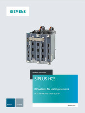
Siemens SIPLUS HCS Series Operating Instructions Manual (208 pages)
IO systems for heating elements, Heating control system
Brand:
Siemens
| Category:
Control Systems
| Size: 3.3 MB
Table of Contents
Table of Contents
5
1 Introduction
11
2 Safety Guidelines
13
Safety Notes
13
Security Information
15
Protective Measures for the HCS4300
15
3 System Overview
17
Area of Application
17
Features
18
System Configuration
20
Central Interface Module (CIM)
21
Function and Design
21
Power Output Module (POM)
23
Function and Design
23
I/O Modules
27
Pm4000 DI/Do
27
Pm4000 U/I
28
PM4000 Temperature
29
EM4315 Expansion Module
30
Design
30
4 Application Planning
31
Shipping
31
Storage
31
Scope of Delivery
32
Installation Location
33
POM4320 Power Rating
36
Power Rating of the POM4320 Highend
38
POM4320 Highend Power Rating
40
POM4320 Highend for Busbar Adapter
40
POM4320 Highend for Wall Mounting
42
5 Installing/Mounting
45
Requirements
45
Installing the Power Output Module (POM)
46
Busbar Mounting
46
Preparations
46
Adjusting the Busbar Adapter
47
Mounting the POM (Busbar Adapter)
49
Panel Mounting
50
POM Mounting (Panel Mounting)
50
Installing the Central Interface Module
51
Installing the EM4315 Expansion Module
52
Installing the I/O Module (PM)
53
6 Wiring
55
Safety Instructions and Guidelines
55
Connecting the Protective Conductor
56
Connecting PROFINET and PROFIBUS Fieldbus
57
Connect 24 V DC Power Supply
57
Connecting the Heating Elements and Three-Phase Line Supply
59
Connecting the Three-Phase Line Supply
59
Connecting Heating Elements
60
Block Diagram POM4320
62
Block Diagrams POM4320 Highend
63
Overview of Connection Types
63
Connection between Phase and Phase (400/480 V)
64
Connection between Phase and Neutral Conductor (230/277 V)
72
Connecting System Interfaces
74
Connecting I/O Modules
76
Pm4000 DI/Do
76
Pm4000 U/I
78
PM4000 Temperature
80
7 Commissioning
83
Requirements
83
Insulation Test
84
8 Configuring/Programming
85
Integrating the HCS4300 into the PROFINET Configuration
85
Integrating the HCS4300 into the PROFIBUS Configuration
85
Device/Hardware Configuration in the TIA Portal
86
PROFINET Device Configuration
86
PROFIBUS Device Configuration
87
Configuration Parameters
88
CIM / POM Configuration Parameters
88
Configuration Parameters for I/O Modules
91
Software Tools for Commissioning Support
93
Overview of Tools for Commissioning Support
93
Configuration Control
95
Configuring
96
Control
96
Slot Assignment
96
Control Data Record
97
Feedback Data Record
99
Transferring Control Data Record in the Startup Program of the CPU
100
Behavior During Operation
102
Examples of Configuration Control
102
Station Master HCS4300
102
9 Functions
107
Function Overview
107
Status and Actual Displays
108
Power Output Control
108
Half-Wave Control
108
Phase Angle Control
110
Soft Starting Function
111
Switch on Heating
112
Soft Start During Heater Operation
113
Channel Control Via Setpoints
113
Channel Control Via Fields
114
Line Voltage Compensation
115
Behavior of the Power Outputs
115
Power Control
116
Parallel Connection of Channels
117
Digital Inputs/Outputs
118
Recording of Analog Measured Line Values
119
Recording of Analog Measured Values
120
Monitoring Functions
121
Phase Connection Monitoring
121
Rotating-Field Test
121
Line Supply Voltage Monitoring
122
Monitoring of the 24 V DC Supply Voltage
122
Frequency Monitoring
122
Temperature Monitoring
123
Power Channel Monitoring
124
Power Channel Monitoring for Loads Connected in Parallel
125
Current Load Monitoring
125
Fault Current Monitoring
125
Power Control Monitoring
126
Monitoring of Adaptive Soft Start
126
10 Communications
127
Cyclic Data Exchange
127
Cyclic Output Data
127
Cyclic Input Data
130
Acyclic Data Exchange
133
Acyclic Data Exchange - Overview
133
Acyclic Output Data
134
Acyclic Input Data
139
Transfer of Diagnostic Alarms to the Controller
142
Transferring Diagnostic Alarms to the Controller: PROFINET
142
Transferring Diagnostic Alarms to the Controller: PROFIBUS
143
Manufacturer-Specific Error Codes
143
11 Process and System Messages, Error Handling
147
Central Interface Module (CIM)
147
Power Output Module (POM)
148
LED Operating Display for POM
148
Fault Reporting through Diagnostics Data
148
I/O Modules
150
12 Servicing and Maintenance
151
Maintenance Work
151
Firmware Update
151
PROFINET Firmware Update
151
PROFIBUS Firmware Update
153
Fuse Replacement
154
Replace Fan
158
Replacing the Power Output Module (POM)
160
Replacing the Central Interface Module (CIM)
162
Replacing an I/O Module
163
Recycling and Disposal
164
13 Technical Specifications
165
Technical Specifications for CIM
165
Technical Specifications POM4320
168
Technical Specifications POM4320 Highend
178
Technical Specifications for I/O Module
184
Technical Specifications for EM4315 Expansion Module
194
Dimension Drawings
197
Appendix
201
Certificates and Approvals
201
A.1 Certificates and Approvals
201
Article Numbers for Spare Parts/Accessories
202
Ordering Data
202
ESD Guidelines
203
A.3 ESD Guidelines
203
Service & Support
205
A.4 Service & Support
205
Application Example
206
Frequently Asked Questions (FAQ)
206
A.4.1 Application Example
206
Index
207
Advertisement
Related Products
Siemens SIPLUS HCS4200 PROFIBUS DP
Siemens SiPass Entro
Siemens SICAM MIC
Siemens SIJECT16
Siemens SIMATIC TDC
Siemens SIMATIC PCS 7 FOUNDATION Fieldbus
Siemens SIDOOR
Siemens SIMATIC NET APE1402
Siemens SIMATIC NET APE1404 ADM
Siemens SIMATIC NET APE1404W7
Siemens Categories
Industrial Equipment
Controller
Control Unit
Oven
Washer
More Siemens Manuals
Login
Sign In
OR
Sign in with Facebook
Sign in with Google
Upload manual
Upload from disk
Upload from URL