Sign In
Upload
Manuals
Brands
Siemens Manuals
Protection Device
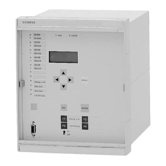
SIPROTEC 7SS52
Siemens SIPROTEC 7SS52 Manuals
Manuals and User Guides for Siemens SIPROTEC 7SS52. We have
1
Siemens SIPROTEC 7SS52 manual available for free PDF download: Operation Manual
Siemens SIPROTEC 7SS52 Operation Manual (211 pages)
Brand:
Siemens
| Category:
Protection Device
| Size: 4.33 MB
Table of Contents
Contents
7
Introduction
17
Chapter Index
17
Data for Selection and Ordering
18
Product Description
21
Application
21
Features
22
Scope of Functions
22
Busbar Protection
22
Circuit-Breaker Failure Protection
23
Isolator Replica
24
Trip Output/Reset
25
Fault Recording
25
Binary Inputs, Trip Outputs, Re-Assignable Alarm Relays and Led's
25
Measuring and Testing Functions
25
Operational and Fault Events
26
Self-Monitoring
26
Versions
26
Bay Units
26
Master Unit
27
Design
28
Fitting of the Modules
29
Device Connections
30
Dimensions
31
Bay Unit
31
Technical Data
37
General Device Data
37
Standards and Guidelines
39
Electrical Tests
39
Service Conditions
41
Inter-Change Ability
41
General Data
42
Ancillary Functions
43
Mode of Operation
45
Operation of Complete Unit
45
Application Functions
47
Basic Principle
48
Stabilization
49
Separate Evaluation of Half-Cycles
51
Weighted Evaluation of the Initial Values
53
Response Threshold, Pick up
54
Summary of the Measuring Method
54
Special Treatment of the Stabilizing Current for the Check Zone
56
Isolator MIMIC
57
Processing of the Isolator Running Status
57
Preferential Treatment During Busbar Coupling Via Isolators
57
Isolator Treatment During Auxiliary Voltage Supply Failure
57
Treatment of the Isolator States in the Event of Wire Breakage
58
Bypass Transfer-Busbar Operation
58
Feeder and Bus Coupler on Different Busbars
59
Feeder and Bus Coupler on the same Busbar Section
60
Status of the Feeder Isolator
61
TRIP Repetition with Current Sensor
63
Unbalancing
64
Pulse Mode
67
Initiation by External Breaker Failure Protection
68
Circuit-Breaker Failure Protection for Busbar Faults
68
Overcurrent Controlled Trip Command
70
Feeder-Selective Trip Release
70
Bay out of Service
74
Event Logging
75
Operation and Indication
75
Alarm Relays and Indications
75
Harware Monitoring
76
Monitoring Functions
76
Software Monitoring
77
Isolator Supervision
79
Current-Controlled Reset of the TRIP Command
80
Cycle Test
81
Installation Instructions
83
Unpacking and Repacking
83
Preparations
83
Connection of the Bay Units in the Bus Coupler Bay
84
Installation and Connection
84
Version for Panel Surface Mounting (FE, ZE)
84
Subrack Version of the Master Unit
85
Bay Unit for Panel or Cubicle Flush Mounting
85
Cubicle Version of the Master Unit
85
Check of the Nominal Data
86
Matching of the Control Voltage for the Binary Inputs
86
Coding of the ZPS Modules
89
Checking the Connections
90
Configuring Examples
91
Marshalling Possibilities
94
Operating Instructions
95
Setting the Master Unit
95
Integrated Keypad/Display Panel
95
Operating Pre-Requisites
96
Communication Software DIGSI
96
Setting the Protection
97
Initial Displays - Blocks 00 and 01
98
Station Lay-Out Data
98
Reading out of Design Data
98
Changing of Station Data
98
Common Data Station Configuration - Block 54
102
Configuration of the Busbar - Block 49
103
System Data
104
Settings
106
Settings for the Busbar Differential Protection
106
Settings for the Pick-Up Characteristics - Block 61
106
Settings for the Differential Current Supervision - Block 63
108
Settings for the Supervisory Functions - Block 63
111
Settings for Breaker Failure Protection Supervision
111
Settings for Isolator Supervision
112
Settings for Linearized Current Transformers
112
Operational Control Features
114
Binary Inputs
114
Taking Bays out of Service - Block 64
115
Test and Control Functions
115
Alarms
118
Marshalling of Binary Outputs and LED-Indications
119
Operational Event Recording - Block 71
122
Fault Events - Block 72
126
Operating the Bay Unit
127
Keypad/Display
127
Prerequisite and Language for Operation
128
Device Settings
130
Setting Via the Integrated Operation - Block 71
130
Marshalling of Binary Inputs, Binary Outputs and LED Indications
131
Marshalling of the Binary Inputs - Block 61
131
Marshalling of the Alarm Relay - Block 62
134
Marshalling of the LED Indications - Block 63
135
Marshalling of the Command Relays - Block 64
137
Test and Control Function - Block 40
139
Read out of Operational Measured Values - Block 57
140
Testing and Comissioning
142
General
142
Test Set-Up
143
Bus-Zone Specific Protection
143
Check Zone
145
Comissioning with Primary Values
153
Checking the Alarms and Trip Signals
154
Switching the Protection into Service
154
Maintenance
155
Maintenance Recommendations
155
Fault Analysis
156
Analysis of Operational Events
156
Checking the Auxiliary Voltage Supply
157
Replacement of Fuses
157
Check of the Leds on the Modules
159
Fault Indication and Analysis of the Fault Buffer
160
Status Events
162
Analysis of Failures in the Communication ZE-FE
164
Repair
167
Storage
169
Appendix
171
Event Records - Block 71 to 76 and 78/ZE - Examples
171
Available Operational and Fault Events
173
Basis for Selection of the Stabilization Factor K
181
Connection Diagrams
182
Connection Diagram Bay Unit
182
Connection Diagram Master Unit
183
Pre-Setting of Binary Inputs and Outputs
187
Table of Direct Addresses - Master Unit (Overview)
192
System and Configuration Data
192
Parameters
195
Commands/Tests
198
Table of Direct Addresses - Bay Unit (Overview)
199
Reference Table for Configuration Parameters - Bay Unit
200
Abbreviations
202
Index
203
Advertisement
Advertisement
Related Products
Siemens SIPROTEC 7SS60
Siemens SIPROTEC 7ST622
Siemens SIPROTEC 7ST63
Siemens Reyrolle 7SR54
Siemens 7SR51
Siemens SIPROTEC 7SJ531
Siemens SIPROTEC easy 7SJ45
Siemens 7SG23 MSCDN - MP2A
Siemens SIPROTEC 7ST61
Siemens SIPROTEC 7SJ64
Siemens Categories
Industrial Equipment
Controller
Control Unit
Oven
Washer
More Siemens Manuals
Login
Sign In
OR
Sign in with Facebook
Sign in with Google
Upload manual
Upload from disk
Upload from URL