Sign In
Upload
Manuals
Brands
Siemens Manuals
Measuring Instruments
SITRANS FST030
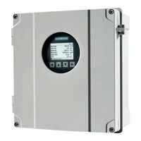
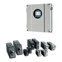
Siemens SITRANS FST030 Flow Meter Manuals
Manuals and User Guides for Siemens SITRANS FST030 Flow Meter. We have
3
Siemens SITRANS FST030 Flow Meter manuals available for free PDF download: Operating Instructions Manual, Function Manual
Siemens SITRANS FST030 Function Manual (350 pages)
Ultrasonic Flowmeters
Brand:
Siemens
| Category:
Measuring Instruments
| Size: 2.65 MB
Table of Contents
Table of Contents
5
1 Introduction
19
Function Manual Scope
19
Purpose of this Documentation
19
Quick Start Wizards
19
Support
19
Product Compatability
20
Document History
20
Device Documentation Package
21
2 Quick Start
23
Quick Commissioning
23
Sensor Settings
23
Process Values
23
Inputs and Outputs
23
Copy Configuration
23
3 Setup
25
Sensor Settings
25
Length Unit
25
Pipe Settings
25
Pipe Class
25
Pipe Size
25
Outer Pipe Diameter
25
Wall Thickness
26
Pipe Material
26
Wall Sound Velocity
26
Liner Settings
27
Inner Pipe Roughness
27
Inner Pipe Diameter
28
Active Compensations
28
Active Compensations - Settings
28
Upstream and Downstream Conditions
28
Disturbed Flow Profile Compensation
28
Disturbed Flow Profile Compensation - Settings
29
Type of Upstream Condition
29
Upstream Distance
29
Upstream Distance - Settings
29
Type of Downstream Condition
29
Downstream Distance
30
Downstream Distance - Settings
30
Medium Characteristics
30
Process Medium Type
30
Expected Sound Velocity
30
Process Temperature
31
Process Pressure
31
Kinematic Viscosity
31
Process Density
32
Sensor Selection
32
Sensor Model
32
Clamp-On Sensor Size
32
Nominal Sensor Frequency
32
Sensor Crystal Projection
33
Sensor Phase Velocity
33
Sensor Inactive Wedge
33
Sensor Fixed Time
34
Mounting Hole Offset
34
Spacing Offset
34
Temperature Code of the Sensor
34
Temperature Compensation Factor
35
Length of Sensor Cables
35
Path Settings
35
Installed Paths
35
Path 1
36
Path 2
38
Necessary Number of Measuring Paths
39
Necessary Number of Measuring Paths - Settings
39
User Calibration
40
Slope
40
Path 1 Offset
40
Path 2 Offset
40
Multipoint Calibration
41
Enable Multipoint Calibration
41
Asymmetric Calibration Table
41
Calibration Point
41
Multipoint Calibration Table
42
Flow Direction
43
Miscellaneous
43
Preamplifier Setting
43
Number of Pulses to be Transmitted
43
Minimum Ringdown Delay
44
Electronic Time Delay
44
Configuration of Test Blocks
44
About
44
Sensor Size
45
Process Values
45
Volume Flow
45
Units
45
Custom Units
46
Custom Conversion Factor
46
Decimal Places
47
Low Flow Cut-Off
47
Alarm and Warning Limits
47
Mass Flow
49
Units
49
Custom Units
49
Custom Conversion Factor
49
Decimal Places
50
Low Flow Cut-Off
50
Alarm and Warning Limits
50
Standard Flow Volume
52
Units
52
Custom Units
52
Custom Conversion Factor
52
Decimal Places
53
Low Flow Cut-Off
53
Alarms and Warning Limits
53
Standard Temperature
55
Standard Pressure
55
Air Density at Standard Conditions
55
Flow Velocity
56
Units
56
Custom Units
56
Custom Conversion Factor
56
Decimal Places
57
Low Flow Cut-Off
57
Alarm and Warning Limits
57
Sound Velocity
59
Units
59
Custom Units
59
Custom Conversion Factor
59
Decimal Places
60
Alarm and Warning Limits
60
Liquident
62
Alarm and Warning Limits
62
Temperature Slope Factor
63
Pressure Slope Factor
63
Density
64
Units
64
Custom Units
64
Custom Conversion Factor
64
Decimal Places
65
Alarm and Warning Limits
65
Kinematic Viscosity
66
Units
66
Decimal Places
67
Alarm and Warning Limits
67
Pressure
69
Units
69
Decimal Places
69
Alarm and Warning Limits
69
Medium Temperature
71
Decimal Places
71
Alarm and Warning Limits
72
Standard Density
73
Units
73
Decimal Places
74
Alarm and Warning Limits
74
Standard Kinematic Viscosity
76
Units
76
Decimal Places
76
Alarm and Warning Limits
76
API Gravity
78
Alarm and Warning Limits
78
Standard API Gravity
79
Alarm and Warning Limits
79
Specific Gravity
81
Alarm and Warning Limits
81
Standard Specific Gravity
83
Alarm and Warning Limits
83
Totalizers
84
Totalizer 1
84
Process Value
84
Units
85
Custom Units
85
Custom Conversion Factor
85
Decimal Places
86
Direction
86
Fail-Safe Behaviour
86
Reset
86
Preset
87
Alarm and Warning Limits
87
Totalizer 2
89
Process Value
89
Units
89
Custom Units
90
Custom Conversion Factor
90
Decimal Places
90
Direction
91
Fail Safe Behaviour
91
Reset
91
Preset
92
Alarm and Warning Limits
92
Totalizer 3
94
Process Value
94
Units
94
Custom Units
95
Custom Conversion Factor
95
Decimal Places
95
Direction
96
Fail-Safe Behaviour
96
Reset
96
Preset
97
Alarm and Warning Limits
97
Reset All Totalizers
99
Inputs and Outputs
99
Current Input
110
Digital Input
111
Channel 1 - Output with HART
111
Loop Current Mode
111
Active Operation (Read Only)
112
PV Selection
112
Direction
112
Loop Current Scale
113
Upper Range Value
113
Lower Range Value
113
Fail-Safe Activation Condition
114
Damping Value
114
Fail-Safe Behaviour
114
Fail-Safe Value
115
Fail-Safe Minimum Time
115
Channel 2 - Output
115
Operation Mode
115
Active Operation (Read Only)
116
Fail-Safe Activation Condition
116
Current Output
116
Frequency Output
119
Pulse Output
122
Status Output
126
Channel 3 - Input/Output
133
Operation Mode
133
Change Operation Mode
133
Active Operation (Read Only)
134
Fail-Safe Activation Condition
134
Current Output
134
Frequency Output
138
Pulse Output
141
Status Output
145
Digital Input
153
Current Input
155
Channel 3 - Relay
160
Operation Mode
160
Status Mode
161
Sensor Alarms (1)
161
Sensor Alarms (2)
161
Process Alarms (1)
162
Process Alarms (2)
162
Process Alarms (3)
162
Process Alarms (4)
163
Totalizer Alarms
163
Device Alarms
164
Device Alarms - Settings
164
Channel 1 Alarms
164
Input/Output Alarms (1)
164
Input/Output Alarms (2)
165
Input/Output Alarms (2) - Settings
165
Simulation Alarms (1)
166
Simulation Alarms (2)
166
Alarm Class
166
NAMUR Status Signal
167
Polarity
167
On Delay
167
Off Delay
168
Channel 4 - Input/Output
168
Operation Mode
168
Change Operation Mode
168
Active Operation (Read Only)
169
Fail-Safe Activation Condition
169
Current Output
169
Frequency Output
172
Pulse Output
176
Status Output
179
Digital Input
187
Current Input
189
Channel 4 - Relay
194
Operation Mode
194
Status Mode
194
Sensor Alarms (1)
194
Sensor Alarms (2)
195
Process Alarms (1)
195
Process Alarms (2)
195
Process Alarms (3)
196
Process Alarms (4)
196
Totalizer Alarms
197
Device Alarms
197
Channel 1 Alarms
197
Input/Output Alarms
198
Simulation Alarms
198
Alarm Class
198
NAMUR Status Signal
199
Polarity
199
On Delay
199
Off Delay
200
Channel 5 - Input
200
Process Value
200
RTD Configuration
200
Calibration
201
Channel 6 - Input
202
Process Value
202
RTD Configuration
202
Calibration
203
Date and Time
204
Current Date and Time
204
Set Date and Time
204
Local Display
204
Brightness
205
Backlight
205
Contrast
206
Damping
206
Damping Value
206
Process Values (1)
206
Process Values (2)
207
View 1
207
View
207
1St Value
208
Graph Scale Mode
208
2Nd Value
208
3Rd Value
209
4Th Process Value
209
6Th Process Value
210
Trend Scale Mode
210
Trend Log Time Window
210
Trend Scale Lower Limit
211
Trend Scale Upper Limit
211
View 2
211
Enable or Disable
211
View
212
1St Value
212
2Nd Process Value
212
3Rd Process Value
213
4Th Process Value
213
6Th Process Value
214
Trend Scale Mode
214
Trend Log Time Window
214
Trend Scale Lower Limit
215
Trend Scale Upper Limit
215
View 3
216
Enable or Disable
216
View
216
1St Value
216
Graphic Scale Mode
217
2Nd Process Value
217
3Rd Process Value
217
4Th Process Value
218
6Th Process Value
219
Trend Scale Mode
219
Trend Log Time Window
219
Trend Scale Lower Limit
220
Trend Scale Upper Limit
220
View 4
220
Enable or Disable
220
View
221
1St Value
221
2Nd Value
221
3Rd Value
222
4Th Value
222
5Th Value
223
Trend Scale Mode
224
Trend Log Time Window
224
Trend Scale Lower Limit
224
Trend Scale Upper Limit
225
View 5
225
Enable or Disable
225
View
225
1St Value
226
2Nd Value
226
3Rd Value
227
4Th Process Value
227
6Th Process Value
228
Trend Scale Mode
228
Trend Log Time Window
228
Trend Scale Lower Limit
229
Trend Scale Upper Limit
229
View 6
229
Enable or Disable
229
View
230
1St Process Value
230
2Nd Process Value
230
3Rd Process Value
231
4Th Process Value
231
6Th Process Value
232
Trend Scale Mode
232
Trend Log Time Window
233
Trend Scale Lower Limit
233
Trend Scale Upper Limit
233
Status Icons
234
4 Maintenance and Diagnostics
235
Identification
235
Long Tag
235
Tag
235
Descriptor
235
Message
236
Location
236
Installation Date
236
Manufacturer
237
Product Name
237
Version (Read Only)
237
Order Number (Read Only)
237
Serial Number
238
FW Version
238
HW Version
238
Final Assembly Number
239
System Type
239
Transmitter Electronics
239
HW Version
239
FW Version
240
Serial Number
240
Order Number
240
Comm. Interface Serial Number
240
Local Display
241
I/O Electronics
241
Dsl
242
Sensor
242
Type (Read Only)
242
Sensor Type (Read Only)
242
Serial Number (Read Only)
242
Serial Number (Read Only)
243
Sensor Type (Read Only)
244
Sensor Firmware Version (Read Only)
244
Sensor Hardware Version (Read Only)
244
Frontend Variant (Read Only)
245
Serial Number (Read Only)
245
Diagnostic Events
245
Active Diagnostic Events
245
Diagnostic Log
245
Clear Diagnostic Log
246
Acknowledge Mode
246
Transmitter Detailed Events (Read Only)
246
Suppression Time
247
Enable Alarms
247
Sensor Events (1)
247
Sensor Events (2)
248
Process Events (1)
248
Process Events (2)
249
Process Events (3)
249
Process Events (4)
249
Totalizer Events
250
Device Events
250
Simulation Events (1)
250
Simulation Events (2)
251
Input/Output Events (1)
251
Input/Output Events (2)
252
Assign Alarm Class
252
14 - Path 1: no Signal
252
15 - Path 2: no Signal
252
148 - Transm. Temp. above Alarm Limit
253
149 - Transm. Temp. below Alarm Limit
253
Maintenance
253
Copy Configuration
253
Spare Part Replacement
254
Transmitter
254
Sensor
255
Operating Time
255
Electronic Part Identification
256
Transmitter Cassette
256
Local Display
257
I/O Cassette
258
Sensor Cassette
259
Diagnostics
260
Sensor
260
Receiver Signal
260
Reynolds Number (Read Only)
260
Path 1
261
Path 2
263
Temperature Monitoring
265
Medium Temperature
265
Transmitter Electronics Temperature
266
DSL Temperature
267
Inputs and Outputs
268
Channel 1 - Output with HART
268
Channel 2 - Output
268
Channel 3 - Input/Output
271
Channel 3 - Relay
273
Channel 4 - Input/Output
273
Channel 4 - Relay
275
Calibration Picture
275
Peak Values
276
Process Value 1
276
Maximum
276
Timestamp at Maximum Value
276
Minimum
277
Timestamp at Minimum Value
277
Reset Peak Values
277
Process Value 2
278
Process Value
278
Maximum
278
Timestamp at Maximum Value
278
Minimum
279
Timestamp at Minimum Value
279
Reset Peak Values
279
Process Value 3
279
Maximum
280
Timestamp at Maximum Value
280
Minimum
280
Timestamp at Minimum Value
281
Reset Peak Values
281
Process Value 4
281
Maximum
282
Timestamp at Maximum Value
282
Minimum
282
Timestamp at Minimum Value
282
Reset Peak Values
283
Characteristics
283
Transmitter
283
Design (Read Only)
283
Hazardous Area Approval (Read Only)
283
Dsl
283
DSL Variant (Read Only)
283
Sensorflash
284
Eject
284
Installed (Read Only)
284
Capacity Total (Read Only)
284
Capacity Available (Read Only)
285
Data Logging
285
Activation
285
Data Logging Mode
286
Logging Interval
286
Process Values
286
Advanced Logging (Expert)
287
Simulation
287
Simulation Inputs and Outputs
287
Channel 1 - Output with HART
287
Channel 2 - Output
288
Channel 3 - Input/Output
289
Relay (3)
291
Channel 4 - Input/Output
292
Channel 4 - Relay
293
Simulation Process Values
294
Enable Simulation
294
Volume Flow
295
Mass Flow
295
Standard Volume Flow
296
Flow Velocity
296
Sound Velocity
296
Liquident
297
Density
297
Kinematic Viscosity
298
Pressure
298
Medium Temperature
299
Standard Density
299
Standard Kinematic Viscosity
299
API Gravity
300
Standard API Gravity
300
Specific Gravity
301
Standard Specific Gravity
301
Auxiliary Temperature
302
Standardizing Factor
302
Liquid Identifier
302
Simulate Alarms
303
Simulation Mode
303
Alarms
303
Alarm Class
306
Alarm Class
307
Audit Trail
307
Parameter Change Log
307
Clear Parameter Change Log (Write Only)
307
Firmware Update Change Log
308
Clear FW Update Change Log (Expert)
308
Self Test
308
Display Test
308
Resets
308
Restore Ordered Configuration (Write Only)
308
Device Restart (Write Only)
309
Firmware Update
309
Advertisement
Siemens SITRANS FST030 Operating Instructions Manual (362 pages)
Ultrasonic flowmeters
Brand:
Siemens
| Category:
Measuring Instruments
| Size: 5.72 MB
Table of Contents
Table of Contents
5
1 Introduction
11
Purpose of this Documentation
11
Product Compatibility
11
Connecting
11
Document History
12
Device Documentation Package
13
Items Supplied
13
Checking the Consignment
14
Security Information
14
Transportation and Storage
15
Technical Data
15
Notes on Warranty
16
2 Safety Notes
17
Preconditions for Safe Use
17
Warning Symbols on the Device
17
Improper Device Modifications
17
Laws and Directives
18
FCC Conformity
18
Conformity with European Directives
18
Requirements for Special Applications
19
Use in Hazardous Areas
19
Commissioning
19
Use in Hazardous Areas
20
Loss of Safety of Device with Type of Protection "Intrinsic Safety Ex I
20
Dust Layers above 5 MM
21
Installation in Hazardous Areas
22
3 Description
25
Design
25
Transmitter
25
Features
25
Applications
28
Approvals
28
Modbus Communication
28
4 Installing/Mounting
29
Installation Location Requirements
29
Installation Instructions
30
Wall Mount Housing Transmitter
30
5 Connecting
33
Basic Safety Notes
33
Missing Pe/Ground Connection
33
Unsuitable Cables, Cable Glands And/Or Plugs
34
Lack of Equipotential Bonding
34
Unprotected Cable Ends
34
Improper Laying of Shielded Cables
35
Insufficient Isolation of Intrinsically Safe and Non-Intrinsically Safe Circuits
35
Incorrect Conduit System
35
Energized Devices
36
Disconnecting Device
36
Device Nameplates
36
Integrating the FST030 with Modbus System
38
System Configuration
39
System Wiring
41
Transmitter Power Supply, Communications and I/Os Connection
43
Preparing for the Connections
44
Connecting Modbus
45
Connecting Channels 2 to 4
46
Input/Output Configuration
48
Connecting Channels 5 and 6
49
Connecting the Power Supply
50
Finishing the Transmitter Connection
51
6 Commissioning
53
Basic Safety Notes
53
Opening Device in Energized State
53
General Requirements
54
Power-Up
54
Local Display
54
Initial Startup
55
Commissioning Via Local Display
56
Wizards
56
Quick Commissioning Wizard
57
Quick Commissioning Wizard (Wizard)
58
Sensor Settings Wizard
58
Process Values Wizard
63
Inputs and Outputs Wizard
65
Communication Wizard
70
Communication Wizard (Wizard)
71
Navigating the Menu Structure
71
Navigation View
71
7 Operating
73
Operating Via the Local Display
73
Display Views
73
Access Control
73
Operating the FST030
74
Fixed Display Texts
74
Reading the Process Values
76
Operating the Totalizers
78
Handling Alarms
79
Reading the Diagnostic Values
81
Reading / Changing Parameters
81
Alphanumeric Parameters
81
Changing the Resolution
82
Parameter Lists
83
8 Service and Maintenance
85
Basic Safety Notes
85
Impermissible Repair of Explosion Protected Devices
85
Recalibration
85
Cleaning
86
Electrostatic Charge
86
Maintenance and Repair Work
86
Service and Maintenance Information
86
Return Procedure
87
Disposal
88
9 Diagnosing and Troubleshooting
89
Unexpected Behavior
89
Application Questionnaire
91
Device Status Icons
92
Fault Codes and Corrective Actions
94
10 Technical Data
117
Power
117
Modbus Interface
117
Inputs
118
Outputs
119
Construction
121
Operating Conditions
122
Approvals
123
Sensorflash
124
11 Dimension Drawings
125
Transmitter
125
Modbus Communication
127
Modbus Addressing Model
127
Coil Configuration
129
A.3 Coil Configuration
129
Modbus Register Mapping
130
Integer Byte Order
132
Float Byte Order
132
Modbus Function Codes
133
Access Control
134
A.8 Access Control
134
Modbus Holding Registers Tables
135
Process Values
135
Totalizers
139
A.9.2 Totalizers
139
Units
142
A.9.3 Units
142
Setup
157
Sensor
157
A.9.4 Setup
157
Process Values
182
A.9.4.2 Process Values
182
Totalizers
193
A.9.4.3 Totalizers
193
Inputs and Outputs
199
Date and Time
272
Local Display
273
A.9.4.6 Local Display
273
Selectable Values Dependent on the View Type
284
Process Value Filter Masks
287
Maintenance and Diagnostics
288
Maintenance & Diagnostics
288
Identification
288
Diagnostic Events
292
Active Events
292
A.9.6 Diagnostic Events
292
Diagnostic Log
296
A.9.6.2 Diagnostic Log
296
Alarm Items
297
A.9.6.3 Alarm Items
297
Diagnostics
304
Sensor
304
A.9.7 Diagnostics
304
Dsl
310
Temperature Monitoring
310
A.9.7.2 Dsl
310
Inputs and Outputs
312
Peak Values
317
A.9.7.5 Peak Values
317
Characteristics
321
Product
321
Transmitter
321
A.9.8 Characteristics
321
Sensor Frontend
322
Sensorflash
322
A.9.8.3 Sensor Frontend
322
Data Logging
323
A.9.9.2 Data Logging
323
Simulation
324
Inputs and Outputs
324
A.9.10 Simulation
324
Process Values
330
A.9.10.2 Process Values
330
Alarms
332
A.9.10.3 Alarms
332
Audit Trail
334
Operating Time
334
A.9.11 Audit Trail
334
Parameter Change Log
335
FW Update Change Log
337
Device Reset
337
Oil Table Settings
338
Communication
340
Service Channel
340
Security
340
Access Management
340
A.9.14 Communication
340
Certificates and Support
343
Certificates
343
Technical Support
343
B.1 Certificates
343
QR Code Label
344
B.3 QR Code Label
344
Simatic Pdm
345
Commissioning with PDM
345
Functions in SIMATIC PDM
345
Supported SIMATIC PDM Versions
345
Initial Setup
345
Integrating the EDD
346
Adding Device to Communication Network
347
Configuring a New Device
348
Wizard - Quick Start Via PDM
349
Wizard - Clamp-On Configuration
350
Wizard - Zero Point Adjustment
350
Changing Parameter Settings Using SIMATIC PDM
351
Parameters Accessed Via Drop-Down Menus
351
Process Variables
353
C.1.12 Process Variables
353
Index
355
Siemens SITRANS FST030 Operating Instructions Manual (356 pages)
Ultrasonic flowmeters
Brand:
Siemens
| Category:
Measuring Instruments
| Size: 3.85 MB
Table of Contents
Table of Contents
3
1 Introduction
9
Purpose of this Documentation
9
Document History
9
Product Compatibility
10
Device Documentation Package
11
Items Supplied
11
Checking the Consignment
12
Security Information
12
Transportation and Storage
13
Notes on Warranty
14
2 Safety Notes
15
Preconditions for Safe Use
15
Warning Symbols on the Device
15
Improper Device Modifications
15
Laws and Directives
15
FCC Conformity
16
Conformity with European Directives
16
Requirements for Special Applications
17
Use in Hazardous Areas
17
Use in Hazardous Areas
18
Loss of Safety of Device with Type of Protection "Intrinsic Safety Ex I
18
Dust Layers above 5 MM
19
Installation in Hazardous Areas
19
3 Description
21
Design
21
Transmitter
21
Features
21
Applications
24
Approvals
24
Modbus Communication
24
4 Installing/Mounting
25
Installation Location Requirements
25
Installation Instructions
26
Wall Mount Housing Transmitter
26
5 Connecting
29
Basic Safety Notes
29
Missing Pe/Ground Connection
29
Unsuitable Cables, Cable Glands And/Or Plugs
30
Lack of Equipotential Bonding
30
Unprotected Cable Ends
30
Improper Laying of Shielded Cables
31
Insufficient Isolation of Intrinsically Safe and Non-Intrinsically Safe Circuits
31
Incorrect Conduit System
31
Energized Devices
32
Disconnecting Device
32
Device Nameplates
32
Integrating the FST030 with Modbus System
34
System Configuration
35
System Wiring
37
Transmitter Power Supply, Communications and I/Os Connection
39
Preparing for the Connections
40
Connecting Modbus
41
Connecting Channels 2 to 4
42
Input/Output Configuration
44
Connecting Channels 5 and 6
46
Connecting the Power Supply
47
Finishing the Transmitter Connection
48
6 Commissioning
51
Basic Safety Notes
51
Opening Device in Energized State
51
General Requirements
51
Power up
52
Local Display
52
Initial Startup
53
Commissioning Via Local Display
54
Wizards
54
Quick Commissioning Wizard
55
Sensor Settings Wizard
56
Process Values Wizard
60
Inputs and Outputs Wizard
62
Communication Wizard
67
Communication Wizard (Wizard)
68
Navigating the Menu Structure
68
Navigation View
68
7 Operating
71
Operating Via the Local Display
71
Display Views
71
Access Control
71
Operating the FST030
72
Fixed Display Texts
72
Reading the Process Values
74
Operating the Totalizers
76
Handling Alarms
77
Reading the Diagnostic Values
79
Reading / Changing Parameters
79
Alphanumeric Parameters
79
Changing the Resolution
80
Parameter Lists
81
8 Service and Maintenance
83
Basic Safety Notes
83
Impermissible Repair of Explosion Protected Devices
83
Recalibration
83
Cleaning
83
Electrostatic Charge
84
Maintenance and Repair Work
84
Service and Maintenance Information
84
On-Board Battery Replacement
85
Return Procedure
86
Disposal
86
9 Diagnostics and Troubleshooting
87
Basic Troubleshooting
87
Troubleshooting Guide
88
Using a Pipe Simulator Test Block (A1)
93
Inspect the Application (A2)
95
Check Sensor Specific Data
97
Verify Sensor Diagnostic Parameters (A3)
97
Improve the Application (A4)
99
Device Status Icons
100
Fault Codes and Corrective Actions
102
10 Technical Data
123
Power
123
Modbus Interface
123
Inputs
124
Outputs
125
Construction
127
Operating Conditions
128
Approvals
129
Sensorflash
129
11 Dimension Drawings
131
Transmitter
131
Modbus Communication
133
Modbus Addressing Model
133
Coil Configuration
135
A.3 Coil Configuration
135
Modbus Register Mapping
136
Integer Byte Order
138
Float Byte Order
138
Modbus Function Codes
138
Access Control
140
Modbus Holding Registers Tables
140
A.8 Access Control
140
Process Values
141
A.9.1 Process Values
141
Totalizers
144
A.9.2 Totalizers
144
Units
147
Setup
160
Sensor
160
Process Values
183
Totalizers
193
Inputs and Outputs
199
Date and Time
267
Local Display
268
Selectable Values Dependent on the View Type
279
Process Value Filter Masks
282
Maintenance and Diagnostics
283
Maintenance & Diagnostics
283
Identification
283
Diagnostic Events
287
Active Events
287
Diagnostic Log
291
Alarm Items
293
Diagnostics
300
Sensor
300
Dsl
305
Temperature Monitoring
305
Inputs and Outputs
307
Peak Values
312
Characteristics
316
Product
316
Transmitter
316
Sensor Frontend
316
Sensorflash
317
Data Logging
318
Simulation
319
Inputs and Outputs
319
A.9.10 Simulation
319
Process Values
325
A.9.10.2 Process Values
325
Alarms
327
A.9.10.3 Alarms
327
Audit Trail
329
Operating Time
329
A.9.11 Audit Trail
329
Parameter Change Log
330
FW Update Change Log
331
Device Reset
332
A.9.12 Device Reset
332
Oil Table Settings
333
Scraper Pig Detection Settings
335
Communication
336
Service Channel
336
Security
336
Access Management
336
A.9.15 Communication
336
Certificates and Support
339
Certificates
339
Technical Support
339
B.1 Certificates
339
QR Code Label
340
B.3 QR Code Label
340
Simatic Pdm
341
Commissioning with PDM
341
Functions in SIMATIC PDM
341
Supported SIMATIC PDM Versions
341
Initial Setup
341
Integrating the EDD
342
Adding Device to Communication Network
343
Configuring a New Device
344
Wizard - Quick Start Via PDM
345
Wizard - Clamp-On Configuration
346
Wizard - Zero Point Adjustment
346
Changing Parameter Settings Using SIMATIC PDM
347
Parameters Accessed Via Drop-Down Menus
348
Process Variables
349
C.1.12 Process Variables
349
Index
351
Advertisement
Advertisement
Related Products
Siemens FST020
Siemens FST020 IP65 NEMA 4X
Siemens SITRANS FST090
Siemens SITRANS FS230
Siemens FS20
Siemens SITRANS FS130
Siemens SITRANS FSS100
Siemens FN2001-A1
Siemens SITRANS FC720
Siemens FCM2004
Siemens Categories
Industrial Equipment
Controller
Control Unit
Oven
Washer
More Siemens Manuals
Login
Sign In
OR
Sign in with Facebook
Sign in with Google
Upload manual
Upload from disk
Upload from URL