Sign In
Upload
Manuals
Brands
Siemens Manuals
Control Unit
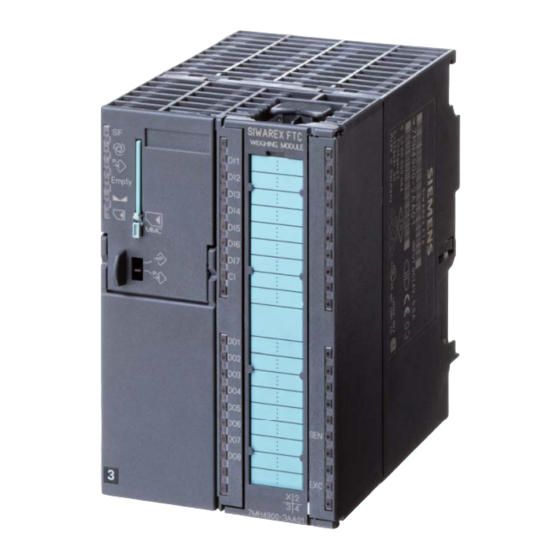
SIWAREX FTC
Siemens SIWAREX FTC Weighing Module Manuals
Manuals and User Guides for Siemens SIWAREX FTC Weighing Module. We have
1
Siemens SIWAREX FTC Weighing Module manual available for free PDF download: Device Manual
Siemens SIWAREX FTC Device Manual (149 pages)
Module for Belt scale
Brand:
Siemens
| Category:
Control Unit
| Size: 1.52 MB
Table of Contents
Revision
2
Table of Contents
4
Basic Knowledge Required
13
Scope of Manual
13
Table 1-2 Overview of Chapter
14
Further Support
15
Scope of Delivery
16
General
17
Product Overview
17
Preface
13
Purpose of Manual
13
Advantages and Benefits
17
Application Range
18
Figure
18
Function
18
Structure
18
Figure
19
Commissioning and Service with Siwatool Ftc_B
20
Figure
20
Firmware Download with Siwatool Ftc_B
21
Reading the Stored Weighing Logs with Siwatool Ftc_B
21
System Integration in Simatic
19
Table
21
Hardware Configuration and Assembly
22
Configuring the Hardware in Simatic
23
Structure to Emc Guidelines
23
Definition: EMC
23
Introduction
23
Table 4-1 Requirements for N Siwarex Ftc Modules
23
Possible Effects of Interference
24
Coupling Mechanisms
24
Five Basic Rules for Guaranteeing EMC
24
Assembly on the Profile Rail
25
Connection and Wiring
26
Connection Areas for SIWAREX FTC
26
Figure
26
Shielding Connection
27
Figure
27
Connection of 24 V Power Supply
28
Connections to Front Terminal
28
Load Cell Connection
28
Table
29
Digital Inputs
30
Figure
30
Table 4-4 Digital Input Connections
31
Counter Input
32
Digital Outputs
32
Table 4-5 Pulse Encoder Connection
32
Figure
32
Table 4-6 Digital Output Connections
33
Table 5-24
33
Figure
33
Analog Output
34
Interface RS 485 for Mettler Toledo Type WM or WMH
34
Table 4-7 Analog Output Connection
34
Figure
34
Figure
35
RS 485 Interface
36
Connecting the Remote Display from Siebert
36
Table 4-9 Rs 485 Connection
36
Figure
36
Connecting the PC for SIWATOOL FTC
37
Table 4-10 Connecting the Pc
37
Figure
37
LED Display Elements
38
Using the Micro Memory Card
38
Table 4-11 Display Elements (Led)
38
Preparing for Operation
39
Application in Ex-Zones
40
Weighing Functions and Parameters
42
General
42
Commands
42
Data Record Overview
43
Dr3 Adjustment Parameters
44
Messages and Diagnosis
44
Table 7-1
45
DR3 - Adjustment Digits 0, 1, 2, 3, 4, for the Zero Point and Adjustment Weights 1, 2, 3, 4
47
Empty
47
Table 5-2 Dr3 Allocation
47
Technical Data
49
DR3 - Characteristic Value Range
51
DR3 - Filter Sequence for the Signal Filter
51
DR3 - Type of Low-Pass Filters
51
DR3 - Depth of Average Value Filters
52
DR3 - Limit Frequency
52
DR3 - Scale Name
52
DR3 - Number of Weight Ranges
52
DR3 - Scale Type
52
DR3 - Activate Zero Setting Upon Switching on
52
DR3 - Activated Zero Setting Upon Switch On, if Scale Tared
53
DR3 - Automatic Zero Adjustment
53
DR3 - Minimum Weight for Weighing Range 1
53
DR3 - Maximum Weight for Weighing Range 1
53
DR3 - Minimum Weight for Weighing Range 1
54
DR 3 - Maximum Weight for Weighing Range 2
54
DR 3 - Maximum Weight for Weighing Range 3
54
DR 3 - Numeral Step for Weighing Range 3
55
DR 3 - Standstill Range
55
DR 3 - Standstill Time
55
DR 3 - Waiting Time for Standstill
55
DR 3 - Maximum Negative Weight for Zero Setting
56
DR 3 - Maximum Negative Weight for Zero Setting Upon Switch on
56
DR 3 - Maximum Positive Weight for Zero Setting
56
DR 3 - Maximum Positive Weight for Zero Setting Upon Switch on
56
DR 3 - Operating Mode
56
DR 3 - Tare Max. Weight T
56
DR 3 - Operating Mode: Belt Scale
57
DR 3 - Operating Mode: Bulk Flow Measurement Device
57
DR 3 - Operating Mode: Force Measurement
57
DR 3 - Operating Mode: Loss-In-Weight Scale
57
DR 3 - Operating Mode: NAWI Emptying Procedure
57
DR 3 - Weighing Operating Mode: NAWI Filling Procedure
57
DR 3 - Load Cell Type
58
DR 3 - Monitoring Time for the Digital Load Cells
58
DR 3 - Conversion Factor
59
DR 3 - Determination Time (Belt Scale Only)
59
DR 3 - Large Weight Unit
59
DR 3 - Length Unit (Belt Scale Only)
59
DR 3 - Regulations
59
DR 3 - Weight Unit
59
Theoretical Adjustment - Adjustment Without Adjustment Weights
60
DR 3 - Minimum Weight for Weighing Range
54
DR 3 - Minimum Weight for Weighing Range 2
54
DR 3 - Minimum Weight for Weighing Range 3
54
Dr 4 Basis Parameter
60
DR 4 - Monitoring Time for Logging
61
DR 4 - Device for the Log Output
61
DR 4 - Basis Weight for Limit Value 1
61
DR 4 - Basis Weight for Limit Value 2
61
Table 5-3 Allocation of Dr
61
DR 4 - Basis Weight for Monitoring the Empty Range
62
DR 4 - Cut-Off Weight Limit Value 1
62
DR 4 - Empty Range
62
DR 4 - Switch-On Weight Limit Value 1
62
DR 4 - Switch-On Weight Limit Value 2
62
DR 4 - Cut-Off Weight Limit Value 2
63
DR 4 - Cut-Off Weight Limit Value 3
63
DR 4 - Switch-On Weight Limit Value 3
63
Dr 5 Belt Scale Parameter
63
DR 5 - Nominal Speed
64
DR 5 - Time Basis for the Belt Speed
64
DR 5 - Pulse Constant
65
DR 5 - Constant Belt Speed
65
DR 5 - Minimum Belt Speed
65
DR 5 - Maximum Belt Speed
65
DR 5 - Reaction Time for Belt Monitoring at Start
65
DR 5 - Reaction Time for Belt Monitoring in Operation
65
DR 5 - Nominal Flow-Rate
65
DR 5 - Effective Belt Length
65
DR 5 - Correction Factor for Belt Loading
65
DR 5 - Minimum Flow-Rate
66
DR 5 - Maximum Flow-Rate
66
DR 5 - Minimum Belt Loading
66
DR 5 - Maximum Belt Loading
66
DR 5 - Maximum Belt Loading for Zero Setting
66
DR 5 - Minimum Belt Loading for Totalizing
66
DR 5 - Delay Time for the Monitoring of the Belt Loading after the Start
66
DR 5 - Delay Time for Monitoring the Belt Loading in Continuous Operation
66
DR 5 - Numeral Step for Totals 1
67
DR 5 - Numeral Step for the Totals 4
67
DR 5 - Material Quantity Per Pulse 1
67
DR 5 - Pulse Duration 1 for the Digital Output
67
DR 5 - Minimum Pause Duration 1 for the Digital Output
67
DR 5 - Material Quantity Per Pulse 2
67
DR 5 - Pulse Duration 2 for the Digital Output
67
DR 5 - Minimum Pause Duration 2 for the Digital Output
67
DR 5 - over and Under-Load Inhibition Time
68
Dr 7 Interfaces
68
DR 7 - Source for the Weight Simulation
73
DR 7 - Decade for Rounding the Decimal Places for the Process Values
73
DR 7 - Force in Service Operation
73
Table 5-4 Allocation of Dr
73
DR 7 - Process Value 1 for Fast Output to the SIMATIC CPU
74
DR 7 - Process Value 2 for Fast Output to the SIMATIC CPU
74
DR 7 - Definition of the Process Alarms 0, 1, 2, 3, 4, 5, 6, 7
74
DR 7 - S7-FB-Life Bit Monitoring Time
75
DR 7 - Input Value for the Adjustment Zero (0 or 4 Ma)
75
DR 7 - Input Value for the End Value (20 Ma)
75
DR 7 - Replacement Value for the Analog Output with OD
75
DR 7 - Source for the Analog Output
75
DR 7 - Current Range for the Analog Output
75
DR 7 - RS232 Printer Baudrate
76
DR 7 - RS232 Transmission Control for Printer
76
DR 7 - Protocol Selection for RS 485
76
DR 7 - Decimal Place for the Remote Display
76
DR 7 - RS 485 Baudrate
76
DR 7 - RS485 Character Frame
77
DR 7 - Definition of the Digital Outputs 1, 2, 3, 4, 5, 6, 7, 8
77
DR 7 - Level Definition for Digital Outputs 1 to 8
77
DR 7 - Replacement Values for DO 1 to 8 with Fault or Output Disable
78
DR 7 - Replacement Values for Digital Outputs with Operating Error
78
DR 7 - Definition of Digital Inputs 0, 1, 2, 3, 4, 5, 6, 7
79
DR 7 - Level Definition for Digital Inputs 1 to 7
79
DR 7 - MMC Log Overflow, MMC Trace Overflow, Target Memory for Trace Function
79
DR 7 - Memory Segment for Trace Function
80
DR 7 - Memory Segment for Log
80
DR 7 - Trace Function Recording Cycle
80
Dr 8 Date / Time
80
Dr 9 Info on Module
81
Table 5-5 Allocation of Dr
81
DR 9 - Info on Module
82
Dr 14 Tilt Angle
82
DR 14 - Tilt Angle Definition for the Belt
82
Dr 15 Tare Entry
82
Table 5-6 Allocation of Dr
82
Table 5-7 Allocation of DR 14
82
Purpose of
82
DR 15 - Tare Entry
83
Dr 16 Weight Simulation Entry
83
DR 16 - Weight Simulation Definition
83
Dr 17 Analog Output Control
83
DR 17 - Ext. Definition for Analog Output
84
DR 18 Control Display for Non-Automatic Weighing Instrument
84
Dr 21 Parameter for Batch Operation
84
DR 21 - Loading Quantity
85
DR 21 - Maximum Loading Time
85
DR 21 - Trailing Weight
85
DR 21 - Log Selection
85
DR 30 Process Status 1 (NAWI, Force Measurement, Belt Scale)
85
Table 5-8 Allocation of Dr
85
DR 30 - NAWI Status Bits
86
DR 30 - Conti-Status Flags
87
DR 30 - Belt Loading in % of the Nominal Load
88
DR 30 - Belt Speed
88
DR 30 - Belt Speed in % of the Nominal Speed
88
DR 30 - G/N Weight
88
DR 30 - G/N Weight_X10
88
DR 30 - Gross Process Value
88
DR 30 - Net Process Value
88
DR 30 - Tare
88
DR 30 - Tare Process Value
88
DR 30 - Belt Load
89
DR 30 - Nominal Load
89
DR 30 - Flowrate 1
89
DR 30 - Flowrate 2
89
DR 30 - Flowrate 3
89
DR 30 - Flowrate in % of the Nominal Flowrate
89
DR 30 - Operating Hours Counter
89
DR 30 - Pulse Counter Value
89
DR 31 Process Status 2 (All Operating Modes)
89
DR 31 - Unfiltered Digital Value
89
DR 31 - Date Time
90
DR 31 - Impedance Actual Value
90
DR 31 - Impedance Reference Value
90
DR 31 - Max. Temperature
90
DR 31 - Operating Error
90
DR 31 - Status of Digital Inputs
90
DR 31 - Unfiltered Digital Value
90
Dr 33 Distribution Memory
90
DR 33 - Distribution Memory 3
90
DR 33 - Distribution Memory
91
Table 5-17
91
DR 33 – Distribution Memory 7
92
Dr 34 Ascii Display Value
92
Dr 35 Encoded Information for Verifiable Display
92
Dr 40 to 43 Log Text 1 to 4
92
Table 5-10 Allocation of Dr
92
Table 5-11 Allocation of Dr
92
Table 5-18
92
Table 5-19
92
Table 5-12 Allocation of Dr
93
Table 5-20
93
DR 44 - Last Log Data
95
DR 44 - Log ID
95
Dr 44 - MMC-ID
95
Dr 44 Last Log
95
Dr 45 String
95
Table 5-21 Process Values for Allocating Log Fields
95
Table 5-22 Allocation of Dr
95
Dr 46 Parameter for Reading MMC Logs in Simatic
96
Table 5-13 Allocation of Dr
96
Table 5-16 Allocation of Dr
96
Table 5-23
96
DR 47 - Log Data
97
DR 47 - Log ID
97
Dr 47 - MMC-ID
97
Dr 47 Requested Log
97
Table 5-9 Allocation of Dr
91
Dr 120/121 Trace - Data Logging
97
Dr 123 Data Content MMC
98
Dr 122 Log Data MMC
99
Table 5-27 Overview of MMC Data
99
Table 5-28 MMC Log
99
Command Groups
100
Commands
100
Command List
101
Table 6-1 Siwarex Ftc Command List
108
Message Paths
110
Message Types
110
Messages and Diagnosis
110
Detection of Messages Using Siwatool Ftc_B
111
Detection of Messages Using Fb Siwa_Ftc
111
Detection of Messages Using the Diagnostic Alarms in the Simatic-Cpu
111
Error
112
Message List Data and Operating Errors
112
Message List Technology Messages
119
Table 7-2 List of Technology Messages
121
Message List of the Operating Messages
122
Table 7-3 List of Operating Messages -Going
122
Table 7-4 List of Operating Messages - Coming
123
General
124
Programming in SIMATIC STEP 7
124
Siwarex Ftc in Hw Config
124
Siwarex Ftc in the Cyclic Step 7 - Program
125
ADDR:= 256, Input, INT
125
DB_SCALE:= 18, Input, INT
126
DB_VECTOR:= 17, Input, INT
126
CMD_IN:= "Db_Scale".I_Cmd_Input, Input, INT
126
SIM_VAL:= "Db_Scale".R_Sim_Value, Input, REAL
126
ANA_OUT:= "Db_Scale".R_Analog_Out_Value, Input, REAL
126
DO_FORCE:= "Db_Scale".B_Dig_Output_Force, Input, BYTE
126
CMD_INPR:= "Db_Scale".Bo_Cmd_In_Progress, Output, BOOL
126
CMD_INPR:= "Db_Scale".Bo_Cmd_Fok, Output, BOOL
126
CMD_ERR:= "Db_Scale".Bo_Cmd_Err, Output, BOOL
127
CMD_ERR_C:= "Db_Scale".B_Cmd_Err_Code, Output, BYTE
127
REF_COUNT:= "Db_Scale".B_Info_Refresh_Count, Output, BYTE
127
PROC_VAL1:= "Db_Scale".R_Process_Value1, Output, REAL
127
PROC_VAL2:= "Db_Scale".W_Process_Value2, Output, DWORD
127
SC_STATUS:= "Db_Scale".Dw_Scale_Status, Output, DWORD
127
ERR_MSG:= "Db_Scale".Bo_Err_Msg, Output, BOOL
127
ERR_MSG_TYPE:= "Db_Scale".B_Err_Msg_Type, Output, BYTE
127
ERR_MSG_C:= "Db_Scale".B_Err_Msg_Code, Output, BYTE
128
FB_ERR:= "Db_Scale".Bo_Fb_Err, Output, BOOL
128
FB_ERR_C:= "Db_Scale".B_Fb_Err_Code
128
Commissioning with a PC - SIWATOOL FTC_B
130
General
130
Windows and Functions in Siwatool Ftc_B
130
Offline Configuration
130
Online Operation
130
Figure
131
Help
131
Advantages of the Firmware Update
132
Firmware-Update with SIWATOOL FTC_B
132
Empty
134
Project Planning in SIMATIC PCS 7
135
Accessories
136
C Onnection and
137
Technical Data
138
Power Supply
138
Power Supply from S7 Backplane Bus
138
Load Cell Connection
138
Table 14-2 Data: Power Supply from S7 Backplane Bus
138
Analog Output
139
Digital Inputs (DI), Digital Outputs (Do)
139
Table 14-3 Data: Load Cell Connection
139
Table 14-4 Data: Analog Output
139
Counter Input CI (for Belt Scale)
140
Rs 232C Interface
140
Rs 485 Interface
140
Table 14-6 Data: Counter Input CI
140
Dimension and Weight
141
Mechanical Requirements and Data
141
Electrical-, EMC- and Climatic Requirements
142
Electrical Protection and Safety Requirements
142
Electromagnetic Compatibility
142
Nvironmental Onditions
144
C Onditions
144
Analog Output
146
Advertisement
Advertisement
Related Products
Siemens SIWAREX MS
Siemens Siwarex U
Siemens SIMATIC Box PC
Siemens SINUMERIK 840D Simodrive 611 digital
Siemens SIMOCODE pro C
Siemens SINUMERIK 840DiE Export version 3.2
Siemens SINAMICS CU240S PN-F
Siemens SIWAREX JB
Siemens SIWAREX FTA
Siemens SIWAREX R
Siemens Categories
Industrial Equipment
Controller
Control Unit
Oven
Washer
More Siemens Manuals
Login
Sign In
OR
Sign in with Facebook
Sign in with Google
Upload manual
Upload from disk
Upload from URL