Sign In
Upload
Manuals
Brands
Siemens Manuals
Circuit breakers
UL 1066
Siemens UL 1066 Manuals
Manuals and User Guides for Siemens UL 1066. We have
1
Siemens UL 1066 manual available for free PDF download: Operating Instructions Manual
Siemens UL 1066 Operating Instructions Manual (334 pages)
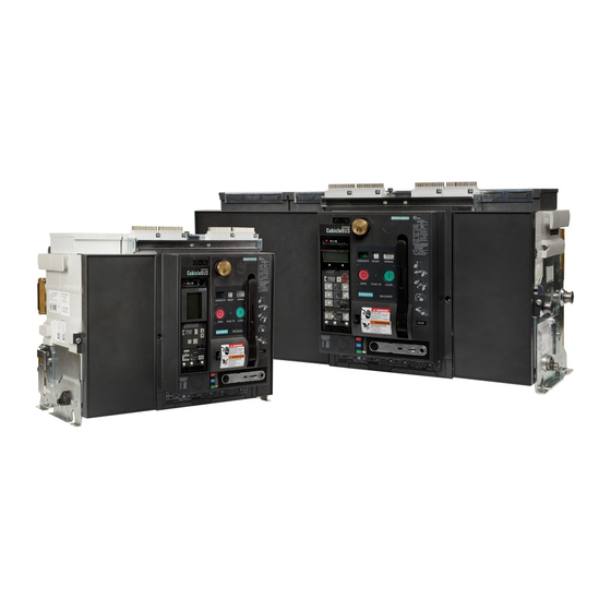
Low Voltage Power Circuit Breaker
Brand:
Siemens
| Category:
Circuit breakers
| Size: 26.2 MB
Table of Contents
Table of Contents
3
1 Overview
6
Circuit Breaker
6
Cradle
7
2 Labels
8
Circuit Breaker Frame Type Label
8
Type Label Circuit Breaker Frame
8
Frame Designation
9
Trip Unit Designation
9
Rating Plug Label
10
Cradle Type Label
10
3 Standard Specifications
11
4 Packing and Lifting
12
Unpacking
12
Weights
12
Lifting with a Crane
13
Lifting with a Lifting Bar Assembly
14
Lifting Bar Assembly (3-Pole)
14
Lifting Bar Assembly (4-Pole)
14
Lifting the Circuit Breaker
15
Lifting the Fuse Carriage (Frame Size III)
15
5 Installation
17
Mounting
18
Mounting Position
18
Mounting on Horizontal Surface - Mounting Tolerances
19
Cubicle and Ventilation
20
Vertical Connections
21
Connecting the Main Conductors
22
Application and Configuration of Fused Circuit Breakers
24
Secondary Wiring
26
Breaker Secondary Disconnect
27
Cradle Secondary Disconnect Block
28
Secondary Disconnect Terminal Blocks
29
Wiring in Cradle
30
Catalog Numbers
31
6 Commissioning
32
Preparation of Draw-Out Circuit Breaker
32
Inserting the Circuit Breaker into the Cradle
32
Positions of the Circuit Breaker in the Cradle
33
Unlocking the Racking Handle / Withdrawing the Racking Handle
34
Racking Circuit Breaker into Connected Position
34
Inserting Racking Handle
34
Charge the Closing Spring
35
Check List for Commissioning
37
Closing the Circuit Breaker
38
Opening the Circuit Breaker
38
Tripping
39
Reclosing a Circuit Breaker Tripped by the Trip Unit
40
Re-Commissioning after Fused Tripping (Not Applicable for 4-Pole)
42
Measures
42
Replacing the Fuses
44
Removing from Service
49
Troubleshooting
50
7 Frame Sizes / Dimension Drawings
52
Frame Size II Drawout
52
Frame Size II Fused
56
Frame Size II, Fixed-Mounted Version
59
Frame Size II, Door Cut-Outs
60
Frame Size III, Fixed-Mounted Version
61
Frame Size III Drawout
62
Frame Size III, Fuse Carriage
65
Frame Size III, Door Cut-Outs
67
External Sensor for Neutral Conductor
69
Further Dimension Drawings
71
8 Circuit Diagrams
72
Terminal Assignment
72
Auxiliary Switches
73
Signaling Switches
74
Shunt Trip, Undervoltage Trip / Electrical Closing Lockout
75
Closing Coil / Electrical CLOSE
76
Motor-Operated Mechanism
77
Remote Bell Alarm Reset
77
Trip Unit Circuitry for ETU745-776
78
With Breaker Status Sensor (BSS) and Metering Module
78
Metering Module Only
79
Breaker Status Sensor (BSS) Only
80
9 Electronic Components
81
Trip Units
81
Overview of Function
81
Trip Unit ETU745
82
Trip Unit ETU748
86
Trip Unit ETU776
88
Indicators
90
Protective Functions
92
ETU Displays
98
Rating Plug
124
Ground-Fault Protection Modules
125
Replace the Trip Unit
129
Internal Trip Unit Self-Test On the Overcurrent Tripping Function
131
Sealing and Locking Device
133
Cubiclebus Modules
134
System Architecture
134
Internal Modules
135
External Cubliclebus Modules
158
External Sensor for Neutral Conductor
171
External Voltage Supply
172
Breaker Data Adapter
173
Application
173
View
173
Indicators
173
Connection Versions
173
Voltage Supply
176
Catalog Numbers
176
Handheld Test Device
177
View
177
Preparations
177
Connecting
178
Voltage Supply
178
Operation
178
Finishing
181
Catalog Numbers
181
10 Reset the Reclosing Lockout and the Bell Alarm
182
Resetting the Bell Alarm
182
Resetting the Bell Alarm with Reclosing Lockout (Optional)
183
Field Installation of a Reclosing Lockout
184
Removing the Automatic Reset Mechanism
185
Installing the Remote Bell Alarm Reset
186
Mounting Remote Reset Solenoid and Cut-Off Switch
186
Connecting Wires
187
Function Test
188
Updating the Options Label
188
11 Shunt Trip / Closing Coil / Undervoltage Release
189
Overview
189
Installing Shunt Trips, Closing Coils, and Undervoltage Devices
190
Installing Optional Signaling Switches on Shunt Trips, Closing Coils, and Undervoltage Devices
191
Setting Delay Times on Undervoltage Release
191
Field Installation of a Cut-Off Switch for Shunt Trips and Closing Coils
192
Mechanical Function Test
194
Connecting Wires
194
Final Tasks
195
Electrical Function Test
195
Updating the Options Label
197
12 Auxiliary and Control Switches
198
Installing Internal Auxiliary Switches S1 - S4
199
Installing the Ready-To-Close Switch S20
200
Trip Signaling Switches
201
Trip Signaling Switches S13, S24, and S26
202
Control Switches - Connecting Wires
203
Communication Switches
203
Connecting Secondary Wiring
203
Updating the Options Label
203
Mechanism Operated Contacts (MOC)
204
MOC Versions
205
MOC Installation Instructions
205
Order Numbers
210
Combination of MOC And Mechanical Interlocking Module
211
Mounting of MOC and Mechanical Interlocking Module on the Cradle
211
13 Motor-Operated Mechanism
212
Installing the Motor Operator
212
Optional Motor Disconnect Switch on the Front Panel
214
Updating the Options Label
215
14 Indicators and Operating Elements
216
Limiting Access to OPEN/CLOSE Buttons
216
EMERGENCY OPEN Button
218
Operations Counter
219
15 Locking Devices
220
Key Locks
220
Breaker Mounted Key Lock
221
Cradle Mounted Key Lock
223
Installing Racking Handle Key Lock
230
Installing a Bell Alarm Cover Key Lock
234
Padlocking Provisions
235
Padlock Locking the Breaker OPEN
236
Padlock Locking Device for Shutter
238
Padlock Locking Device for Guide Rails
239
Padlock Locking Device for Racking Handle
239
Padlock Locking Device for Spring Charging Lever
239
CLOSE/OPEN Padlock Kit
241
16 Sealing Covers
243
17 Mechanical Interlocks
244
Field Installation of CLOSE / OPEN Buttons Blocking Device
245
Cubicle Door Interlock
246
Installing the Interlock Mechanism to the Cradle
247
Cubicle Door Interlock Drill Pattern
247
Installing Catch on the Cubicle Door
248
Function Check
248
Interlock to Prevent Racking with Cubicle Door Open
249
Coding between Circuit Breaker and Cradle
250
18 Additional Options for the Cradle
251
Shutter
251
Field Installation
252
Catalog Numbers
258
Truck Operated Contacts - TOC (Cradle Accessory)
259
19 Mechanical Circuit Breaker Interlocking
262
Configurations
262
General Notes
263
Mechanical Interlocking Two Sources (Open Transition)
264
Mechanical Interlocking Two Sources with a Tie Circuit Breaker (Open Transition)
265
Mechanical Interlocking Feeder Circuit Breakers (Single Load, Open Transition)
266
Mechanical Interlocking Three Sources (Open Transition to Standby System)
267
Mechanical Interlocking Source and Tie Circuit Breaker (Open Transition to Standby System)
268
Installing Interlocking Module
269
Installing Intermediate Shaft and Coupling
269
Fitting Interlocking Module
272
Mounting the Bowden Cables
273
Function Check
275
20 Arc Chute Covers
276
Field Installation
276
Catalog Numbers
278
21 Door Sealing Frame
279
22 Plexiglas Breaker Cover
281
23 Maintenance
283
Preparation for Maintenance
284
Opening the Circuit Breaker and Discharging the Closing Spring
284
Removing the Circuit Breaker from the Cradle
285
Changing Front Panel
286
Removing Front Panel
286
Reinstalling the Front Panel
286
Checking Arc Chutes
287
Removing Arc Chutes
288
Visual Inspection
288
Installing Arc Chutes
289
Catalog Numbers
290
Inspection of Arc Chute Covers
291
Checking Contact Erosion
292
Replacing the Circuit Breaker Internal Contact Assemblies
293
Removing Front Panel
294
Removing Arc Chutes
294
Removing Vertical Adapter
294
Removing Pole Assemblies
294
Installing Pole Assemblies
299
Adjusting the Contact Wear Indicator
304
Attaching the Vertical Adapter
305
Order Numbers
308
Attaching the Front Panel
309
Installing the Arc Chutes
309
Mechanical Function Test
309
Exchanging the Primary Disconnects
310
Exchanging the Finger Cluster
310
Catalog Numbers
311
Exchanging the Stab Tip
312
Catalog Numbers
313
Cleaning and Greasing the Circuit Breaker
314
24 Technical Data
316
25 Abbreviations
326
26 Glossary
330
27 Index
332
Advertisement
Advertisement
Related Products
Siemens UL1066 WL
Siemens UL 489
Siemens Milltronics Pointek ULS200
Siemens ULTRAMAT 6
Siemens VersiCharge Ultra 50
Siemens ULTRAMAT/OXYMAT 6E
Siemens VersiCharge Ultra 175
Siemens ULTRAMAT 6 Series
Siemens UL 508A
Siemens ULTRAMAT 23 Series
Siemens Categories
Industrial Equipment
Controller
Control Unit
Oven
Washer
More Siemens Manuals
Login
Sign In
OR
Sign in with Facebook
Sign in with Google
Upload manual
Upload from disk
Upload from URL