Sign In
Upload
Manuals
Brands
Sony Manuals
Stereo System
HCD-FL7D - System Components
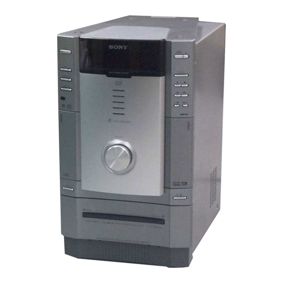
Sony HCD-FL7D - System Components Manuals
Manuals and User Guides for Sony HCD-FL7D - System Components. We have
3
Sony HCD-FL7D - System Components manuals available for free PDF download: Service Manual, Operating Instructions Manual
Sony HCD-FL7D - System Components Service Manual (204 pages)
Brand:
Sony
| Category:
Receiver
| Size: 28.51 MB
Table of Contents
Table of Contents
5
Audio Tracks
4
Schematic Diagram - MB Board (1/7)
5
1 Servicing Notes
7
2 General
9
Location of Controls
9
Setting the Clock
10
3 Disassembly
11
Disassembly Flow
11
Top Panel Assy
12
Back Cover
12
Side Panel (A)/(B)
13
Case
13
Front Panel Assy
14
GC Board
14
Tape Mechanism Assy
15
Belt
15
SW Board, HEAD (A) Board, HEAD (B) Board
16
DVD Mechanism Block
16
DSP Board
17
DVD Mechanism Deck (CDM53N-DVBU14)
17
Fitting Base (Guide) Assy, Bracket (Chassis), Magnet Assy
18
Base Unit (DVBU14)
18
Tray (Sub)
19
Chassis (Mold B) Section, Stocker Section, Slider (Selection)
19
VIDEO Board
20
SUB TRANS Board
20
Back Cover Section
21
Tel 13942296513
21
TRANS Board
21
SP RELAY Board
22
4 Assembly
23
Gears Installation
23
Slider (Selection) Installation
24
Stocker Section Installation
24
Chassis (Mold B) Section Installation
25
5 Test Mode
26
6 Mechanical Adjustments
35
7 Electrical Adjustments
35
Deck Section
35
8 Diagrams
38
Block Diagram - RF SERVO Section
38
Block Diagram - TUNER/TAPE DECK Section
39
Block Diagram - AUDIO DSP Section (1/2)
40
Block Diagram - AUDIO DSP Section (2/2)
41
Block Diagram - POWER AMP Section
42
Block Diagram - VIDEO Section
43
Block Diagram - DISPLAY/POWER SUPPLY Section
44
Note for Printed Wiring Boards and Schematic Diagrams
45
Printed Wiring Board - RF Board
46
Schematic Diagram - RF Board
47
Printed Wiring Board - MB Board (Component Side)
48
Printed Wiring Board - MB Board (Conductor Side)
49
Ao y
49
Schematic Diagram - MB Board (1/7)
50
Schematic Diagram - MB Board (2/7)
51
Schematic Diagram - MB Board (3/7)
52
Schematic Diagram - MB Board (4/7)
53
Schematic Diagram - MB Board (5/7)
54
Schematic Diagram - MB Board (6/7)
55
Schematic Diagram - MB Board (7/7)
56
Printed Wiring Boards - CHANGER Section
58
Schematic Diagram - CHANGER Section
59
Printed Wiring Boards - CD DOOR Section
60
Schematic Diagram - CD DOOR Section
61
Printed Wiring Board - SW Board
62
Schematic Diagram - SW Board
63
Printed Wiring Boards - TC DOOR Section
64
Schematic Diagram - TC DOOR Section
65
Printed Wiring Board - MC Board
66
Schematic Diagram - MC Board
67
Printed Wiring Board - DSP Board (Component Side)
68
Printed Wiring Board - DSP Board (Conductor Side)
69
Schematic Diagram - DSP Board (1/3)
70
Schematic Diagram - DSP Board (2/3)
71
Schematic Diagram - DSP Board (3/3)
72
Schematic Diagram - CENTER SW AMP Board
73
Printed Wiring Board - CENTER SW AMP Board - (US, CND, AEP, UK Models)
74
Q Q
75
7 - CENTER SW AMP Board - (EA, MX, SP, KR Models)
75
Printed Wiring Board - FRONT REAR AMP Board
76
Schematic Diagram - FRONT REAR AMP Board
77
Printed Wiring Boards - SPEAKER Section
78
Schematic Diagram - REGULATOR Board
79
Schematic Diagram - SPEAKER Section (1/2)
80
Schematic Diagram - SPEAKER Section (2/2)
81
Printed Wiring Board - GC Board
82
Schematic Diagram - GC Board
83
Printed Wiring Boards - PANEL Section
84
Schematic Diagram - PANEL Section
85
Printed Wiring Board - MIC Board - (EA, MX, SP, KR Models)
86
Schematic Diagram - MIC Board - (EA, MX, SP, KR Models)
87
Printed Wiring Board - VIDEO Board
88
Schematic Diagram - VIDEO Board
89
Printed Wiring Board - SUB TRANS Board - (US, CND, AEP, UK Models)
90
Printed Wiring Board - SUB TRANS Board - (EA, MX, SP, KR Models)
91
Schematic Diagram - SUB TRANS Board
92
Printed Wiring Board - TRANS Board
94
Schematic Diagram - TRANS Board
95
IC Pin Function Description
104
9 Exploded Views
124
Case Section
124
Front Panel Section-1
125
Front Panel Section-2
126
Front Panel Section-3
127
Front Panel Section-4
128
Chassis Section-1
129
Chassis Section-2
130
Chassis Section-3
131
Chassis Section-4
132
DVD Mechanism Deck Section-1 (CDM53N-DVBU14)
133
DVD Mechanism Deck Section-2 (CDM53N-DVBU14)
134
DVD Mechanism Deck Section-3 (CDM53N-DVBU14)
135
DVD Mechanism Deck Section-4 (CDM53N-DVBU14)
136
Base Unit Section (DVBU14)
137
Tape Mechanism Deck Section (TCM-230AWR41CS)
138
10 Electrical Parts List
139
CND : Canadian
139
EA : Saudi Arabia
139
KR : Korean
139
MX : Mexican
139
SP : Singapore
139
3 7 63 1515 0 2 9 9 4 2 88 9 9 Memo
169
New/Former Type Description
170
Diagrams
172
Note for Printed Wiring Boards and Schematic Diagrams
172
Schematic Diagram - MB Board (2/7)
173
Schematic Diagram - MB Board (3/7)
174
Schematic Diagram - MB Board (4/7)
174
Schematic Diagram - MB Board (5/7)
175
Schematic Diagram - MB Board (6/7)
175
Schematic Diagram - MB Board (7/7)
176
MB Board (Component Side)
180
MB Board (Conductor Side)
181
Printed Wiring Boards - CD DOOR Section
182
Schematic Diagram - CD DOOR Section
183
Printed Wiring Boards - TC DOOR Section
184
Schematic Diagram - TC DOOR Section
185
Printed Wiring Board - GC Board
186
Schematic Diagram - GC Board
187
Printed Wiring Boards - PANEL Section
188
Schematic Diagram - PANEL Section
189
Printed Wiring Board - MIC Board - (EA, MX, SP, KR Models)
190
Schematic Diagram - MIC Board - (EA, MX, SP, KR Models)
191
Ao y U163
195
Advertisement
Sony HCD-FL7D - System Components Service Manual (204 pages)
Brand:
Sony
| Category:
Stereo System
| Size: 19.39 MB
Table of Contents
Table of Contents
5
Service Manual
1
Leakage Test
3
Audio Tracks
4
1 Servicing Notes
7
2 General
9
Location of Controls
9
Setting the Clock
10
3 Disassembly
11
Disassembly Flow
11
Top Panel Assy
12
Back Cover
12
Side Panel (A)/(B)
13
Case
13
Front Panel Assy
14
GC Board
14
Tape Mechanism Assy
15
Belt
15
SW Board, HEAD (A) Board, HEAD (B) Board
16
DVD Mechanism Block
16
DSP Board
17
DVD Mechanism Deck (CDM53N-DVBU14)
17
Fitting Base (Guide) Assy, Bracket (Chassis), Magnet Assy
18
Base Unit (DVBU14)
18
Tray (Sub)
19
Chassis (Mold B) Section, Stocker Section, Slider (Selection)
19
VIDEO Board
20
SUB TRANS Board
20
Back Cover Section
21
TRANS Board
21
SP RELAY Board
22
4 Assembly
23
Gears Installation
23
Slider (Selection) Installation
24
Stocker Section Installation
24
Chassis (Mold B) Section Installation
25
5 Test Mode
26
6 Mechanical Adjustments
35
7 Electrical Adjustments
35
Deck Section
35
8 Diagrams
38
Block Diagram - RF SERVO Section
38
Block Diagram - TUNER/TAPE DECK Section
39
Block Diagram - AUDIO DSP Section (1/2)
40
Block Diagram - AUDIO DSP Section (2/2)
40
Block Diagram - POWER AMP Section
42
Block Diagram - VIDEO Section
43
Block Diagram - DISPLAY/POWER SUPPLY Section
44
Note for Printed Wiring Boards and Schematic Diagrams
45
Printed Wiring Board - RF Board
46
Schematic Diagram - RF Board
47
Printed Wiring Board - MB Board (Component Side)
48
Printed Wiring Board - MB Board (Conductor Side)
49
Schematic Diagram - MB Board (1/7)
51
Schematic Diagram - MB Board (2/7)
52
Schematic Diagram - MB Board (3/7)
53
Schematic Diagram - MB Board (4/7)
55
Schematic Diagram - MB Board (5/7)
56
Printed Wiring Boards - CHANGER Section
58
Schematic Diagram - CHANGER Section
59
Schematic Diagram - CD DOOR Section
61
Printed Wiring Board - SW Board
62
Schematic Diagram - SW Board
63
Printed Wiring Boards - TC DOOR Section
64
Schematic Diagram - TC DOOR Section
65
Printed Wiring Board - MC Board
66
Schematic Diagram - MC Board
67
Printed Wiring Board - DSP Board (Component Side)
68
Printed Wiring Board - DSP Board (Conductor Side)
69
Schematic Diagram - DSP Board (1/3)
70
Schematic Diagram - DSP Board (2/3)
71
Schematic Diagram - DSP Board (3/3)
72
Schematic Diagram - CENTER SW AMP Board
73
Printed Wiring Board - CENTER SW AMP Board - (US, CND, AEP, UK Models)
74
Printed Wiring Board - CENTER SW AMP Board - (EA, MX, SP, KR Models)
75
Printed Wiring Board - FRONT REAR AMP Board
76
Schematic Diagram - FRONT REAR AMP Board
77
Printed Wiring Boards - SPEAKER Section
78
Schematic Diagram - REGULATOR Board
79
Schematic Diagram – SPEAKER Section (1/2)
80
Schematic Diagram - SPEAKER Section (1/2)
81
Schematic Diagram - GC Board
83
Printed Wiring Boards - PANEL Section
84
Schematic Diagram - PANEL Section
85
Printed Wiring Board - MIC Board - (EA, MX, SP, KR Models)
86
Schematic Diagram - MIC Board - (EA, MX, SP, KR Models)
87
Printed Wiring Board - VIDEO Board
88
Schematic Diagram - VIDEO Board
89
Printed Wiring Board - SUB TRANS Board - (US, CND, AEP, UK Models)
90
Printed Wiring Board - SUB TRANS Board - (EA, MX, SP, KR Models)
91
Schematic Diagram - SUB TRANS Board
92
Printed Wiring Board – TRANS Board
94
Schematic Diagram - TRANS Board
95
Dsp Board
101
Sp Relay Board
102
IC Pin Function Description
104
9 Exploded Views
124
Case Section
124
Front Panel Section-1
125
Front Panel Section-2
126
Front Panel Section-3
127
Front Panel Section-4
127
Chassis Section-1
129
Chassis Section-2
129
Chassis Section-3
131
Chassis Section-4
132
DVD Mechanism Deck Section-1 (CDM53N-DVBU14)
133
DVD Mechanism Deck Section-2 (CDM53N-DVBU14)
134
DVD Mechanism Deck Section-3 (CDM53N-DVBU14)
135
DVD Mechanism Deck Section-4 (CDM53N-DVBU14)
136
Base Unit Section (DVBU14)
137
Tape Mechanism Deck Section (TCM-230AWR41CS)
138
10 Electrical Parts List
139
CND : Canadian
139
EA : Saudi Arabia
139
KR : Korean
139
MX : Mexican
139
SP : Singapore
139
Supplement-1
169
New/Former Type Description
170
1 Diagrams
172
Note for Printed Wiring Boards and Schematic Diagrams
172
Schematic Diagram - MB Board (1/7)
173
Schematic Diagram - MB Board (2/7)
173
Schematic Diagram - MB Board (3/7)
174
Schematic Diagram - MB Board (4/7)
174
Schematic Diagram - MB Board (5/7)
175
Schematic Diagram - MB Board (6/7)
176
Schematic Diagram - MB Board (7/7)
176
MB Board (Component Side)
180
Printed Wiring Board - MB Board (Conductor Side)
181
Printed Wiring Boards - CD DOOR Section
182
Schematic Diagram - CD DOOR Section
183
Printed Wiring Boards - TC DOOR Section
184
Schematic Diagram - TC DOOR Section
185
Printed Wiring Board - GC Board
186
Schematic Diagram - GC Board
187
Printed Wiring Boards - PANEL Section
188
Schematic Diagram - PANEL Section
189
Printed Wiring Board - MIC Board - (EA, MX, SP, KR Models)
190
Schematic Diagram - MIC Board - (EA, MX, SP, KR Models)
191
2 Electrical Parts List
192
Revision History
204
Sony HCD-FL7D - System Components Operating Instructions Manual (76 pages)
Sony Operating Instruction Display Side Hi-Fi Component System DHC-FL7D, DHC-FL5D
Brand:
Sony
| Category:
Stereo System
| Size: 0.71 MB
Table of Contents
Operating Instructions
1
Important Notice
3
Table of Contents
4
This System Can Play the Following Discs
6
List of Buttons and Reference Pages
7
Main Unit
7
Remote Control
8
Digipad Operations
9
Getting Started
10
Hooking up the System
10
Connect the Speakers
11
Inserting Three R6 (Size AA) Batteries into the Remote
13
Setting up Your Speakers
14
Specifying the Speaker Parameters
15
Setting the Clock
16
DVD/VIDEO CD/CD/Super Audio CD/MP3
17
Playing Discs
17
Loading a Disc
17
Playing a Disc
17
Normal Play/Shuffle Play/Repeat
17
Play/Scan/Slow-Motion Play
17
Other Operations
18
Playing a Disc with MP3 Audio Tracks
19
Playing a Disc with Mp3 Audio Tracks
20
Creating Your Own Program
22
Program Play
22
Resuming Playback from the Point You
23
Stopped the Disc
23
Resume Play
23
Playing Repeatedly
24
Repeat Play
24
Playing Dvds Using the Menu
25
Playing VIDEO Cds with PBC Functions
25
PBC Play
25
Ver. 2.0 PBC Play
25
Setting up for DVD/VIDEO CD/CD
26
Using the Setup Display
26
Setting the Display or Sound Track Language
27
Language Setup
27
Settings for the Display
28
Screen Setup
28
Custom Settings
29
Custom Setup
29
Speaker Settings
30
Speaker Setup
30
Viewing Information about the Disc
32
Checking the Playing Time and Remaining Time
32
Sound Adjustment
33
Changing the Sound
33
Enjoying Movies
35
Searching for a Title/Chapter /Track/Index
35
Changing the Angles
36
Displaying the Subtitles
36
Using Various Additional Functions
37
Locking Discs
37
Custom Parental Control/ Parental Control
37
Limiting Playback by Children
38
Tuner
41
Presetting Radio Stations
41
Listening to the Radio
42
Using the Radio Data System (RDS)
43
Tape
44
Loading a Tape
44
Playing a Tape
44
Recording to a Tape
45
CD Synchro Recording/High-Speed
45
Edit
45
Dubbing/Recording Manually/Program Edit
45
Program Edit
46
Timer-Recording Radio Programs
47
Sound Adjustment
48
Adjusting the Sound
48
Selecting the Sound Effect
48
Enjoying Dolby Pro Logic II
49
(DHC-FL7D Only)
49
Adjusting the Sound Effects
50
Creating a Personal Sound Effect File
51
Personal File
51
Display
52
Turning off the Display
52
Power Saving Mode
52
Using the Display
52
Other Features
53
To Adjust the Brightness of the Display
53
To Listen to Multi Channel Sound
53
Singing Along: Karaoke
54
About Indicators
55
Falling Asleep to Music
55
Sleep Timer
55
Waking up to Music
56
Daily Timer
56
Optional Components
57
Hooking up Optional Components
57
Listening to Audio from a Connected Component
58
Recording Audio from a Connected Component
59
Recording on a Connected Component
59
Troubleshooting
60
Problems and Remedies
60
Tape Deck
63
Additional Information
65
Precautions
65
Specifications
67
Glossary
70
Language Code List
73
Control Menu Item List
74
Setup Display Item List
75
Advertisement
Advertisement
Related Products
Sony HCD-FL3
Sony HCD-F250AV - Compact Disc Receiver System
Sony HCD-F50
Sony HCD-F100
Sony HCD-FX300i CND
Sony HCD-FX300i SP
Sony HCD-FX300i TW
Sony HCD-FX300i TH
Sony HCD-FX300i AUS
Sony HCD-FX300i E51
Sony Categories
Laptop
TV
CD Player
Camcorder
Digital Camera
More Sony Manuals
Login
Sign In
OR
Sign in with Facebook
Sign in with Google
Upload manual
Upload from disk
Upload from URL