Sign In
Upload
Manuals
Brands
Toshiba Manuals
Air Conditioner
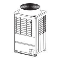
MMY-MAP1206FT8P
Toshiba MMY-MAP1206FT8P Manuals
Manuals and User Guides for Toshiba MMY-MAP1206FT8P. We have
1
Toshiba MMY-MAP1206FT8P manual available for free PDF download: Service Manual
Toshiba MMY-MAP1206FT8P Service Manual (354 pages)
Brand:
Toshiba
| Category:
Air Conditioner
| Size: 33.31 MB
Table of Contents
Table of Contents
2
Safety Caution
6
Refrigerant (R410A)
26
Wiring Diagrams
28
Outdoor Unit
28
Single Port FS Unit
34
Multi Port FS Unit
36
Single Port FS Unit (Long Piping Model)
38
Parts Rating
39
Outdoor Unit (50Hz Model: MMY-MAP***6FT8*P*)
39
Outdoor Unit (60Hz Model: MMY-MAP***6FT7*P)
40
Outdoor Inverter (50/60Hz Model: MMY-MAP***6FT8/7*P*)
41
Multi Port FS Unit (50/60Hz Model: RBM-Y1801F4PE/PE2, RBM-Y1801F6PE/PE2)
42
Single Port FS Unit (Long Piping Model) 50/60Hz Model : RBM-Y1124FE/FE2, RBM-Y1804FE/FE2, RBM-Y2804FE/FE2)
42
Parts Layout in Outdoor Unit
43
Parts Layout in Inverter Assembly
46
Outdoor (Inverter) Print Circuit Board
49
Interface P.C. Board (MCC-1673)
49
Inverter P.C. Board for Compressor (MCC-1660) A3-IPDU
50
Inverter P.C. Board for Compressor (MCC-1669) A3-IPDU
51
Inverter P.C. Board for Fan Motor (MCC-1659) FAN-IPDU
52
Noise Filer PC Board (MCC-1608 -A, -B)
53
Refrigerant Piping Systematic Drawing
54
Combined Refrigerant Piping System Schematic Diagrams
64
Single Cooling Mode (Operation of Cooling Only) When Outside Temperature Is High (Standard: 10°C or Higher) / Defrost Mode
64
(Standard: 10°C or Lower)
65
Single Heating Mode (Operation of Heating Only)
66
Hot Gas Defrost Mode (Operation of Single Heating Only)
67
Collective Cooling Mode
68
(Operating Cooling Function Mainly, Collective Operation of Cooling and Heating Operation)
68
Collective Heating Mode
69
(Operating Heating Function Mainly, Collective Operation of Cooling and Heating Operation)
69
Emergency Operation (Single Cooling Operation at Backup of the Header Unit)
70
Emergency Operation (Single Heating Operation at Backup of the Header Unit)
71
Refrigerant Recovery (During Pump-Down Operation) of the Troubled Outdoor Unit (in Case of Trouble of Follower Unit)
72
Control Outline
73
Indoor Unit
73
Outdoor Unit
79
Applied Control for Outdoor Unit
88
Outdoor Fan High Static Pressure Shift
88
Priority Operation Mode Setting
89
Applied Control of Outdoor Unit
91
Power Peak-Cut Control (Standard)
92
Power Peak-Cut Control (Extended)
93
Snowfall Fan Control
94
External Master ON/OFF Control
94
Night Operation (Sound Reduction) Control
95
Operation Mode Selection Control
96
Trouble/Operation Output
97
Compressor Operation Output
98
Operating Rate Output
99
Test Operation
100
Procedure and Summary of Test Operation
100
Check Items before Test Operation (before Powering-On)
101
Check at Main Power-On
105
Address Setup
106
Precautions
106
Address Setup and Check Procedure
106
Address Setup Procedure
107
Check after Address Setup When Central Control System Is Connected
120
Setting When Connecting Multiple Indoor Units to a FS (Flow Selector) Unit
121
How to Set up the Cooling Only Indoor Unit
126
Troubleshooting in Test Operation
127
A Check Code Is Displayed on the Remote Controller
127
Operation from the Indoor Remote Controller Is Not Accepted, and a Check Code Is Displayed on the 7-Segment Display of the Interface PC Board of the Header Unit
128
There Is no Display of a Check Code on the 7-Segment Display on the Interface
128
PC Board of the Header Unit, Although There Is Indoor Unit that Is Not Accepting Operation from the Indoor Remote Controller
128
In Checking the Number of Connected Outdoor Units and Connected Indoor Units
129
Outdoor/Indoor Units that Do Not Operate in a Test Operation.)
129
Test Operation Check
131
Fan Check
131
Single Cooling/Single Heating Test Operation Check
132
Service Support Function
135
Check Function for Connecting of Refrigerant and Control Lines
135
Function to Start/Stop (ON/OFF) Indoor Unit from Outdoor Unit
138
Check Code Clearing Function
144
Remote Controller Distinction Function
146
Pulse Motor Valve (PMV) Forced Open/Close Function in Indoor Unit
147
Pulse Motor Valve (PMV) Forced Open Fully/Close Fully Function in Outdoor Unit
147
Solenoid Valve Forced Open/Close Function in Outdoor Unit
148
Fan Operation Check in Outdoor Unit
149
Abnormal Outdoor Unit Discrimination Method by Fan Operating Function
150
Manual Adjustment Function of Outside Temperature (TO) Sensor
151
Refrigerant Leakage Detection
153
Monitor Function of Remote Controller Switch
154
Smms Wave Tool for Smartphone
156
Prohibition/Permission of the NFC Setting
156
Confirmation for the Generation of the Trouble of the NFC
157
DRED (Demand Response Enabling Device)
158
Troubleshooting
160
Overview
160
Troubleshooting Method
161
Troubleshooting Based on Information Displayed on Remote Controller
167
Check Codes Displayed on Remote Controller and SHRM-E Outdoor Unit (7-Segment Display on I/F Board) and Locations to be Checked
172
Diagnosis Procedure for each Check Code
188
7-Segment Display Function
220
Oil Level Judgment Display
226
SHRM-E Outdoor Interface P.C. Board Function Setting Exchange Table
227
Leakage/Clogging of Refrigerating Cycle Circuit
230
Sensor Characteristics
239
Pressure Sensor Output Check
242
Backup Operation
244
(Emergency Operation)
244
Note for Backup Operation
244
Compressor Backup Operation Setting
245
Outdoor Unit Backup Operation Setting
248
Follower Outdoor Unit Backup Operation Setting (Failure of Follower Outdoor Unit)
248
Header Outdoor Unit Backup Operation Setting (Failure of Header Outdoor Unit)
250
Outdoor Unit Refrigerant Recovery Method
253
Refrigerant Recovery from Failed Outdoor Unit (Pump-Down)
253
Note for Refrigerant Recovery Operation
253
Refrigerant Recovery Procedure a (Case of no Outdoor Unit Backup Operation Setting)
253
Refrigerant Recovery Procedure B (Case of Outdoor Unit Backup Operation Setting)
256
How to Operate System While Failed Outdoor Unit Being Repaired
258
Work Procedure after Repair
259
Replacing Compressors
260
Compressor Replacement Procedure (Outline)
260
Replacement of Compressors
261
Check Procedure to Search Cause of Compressor Oil Shortage
266
Outdoor Unit Parts Replacement Methods
270
C. Board Exchange Procedures
286
Replacement of Outdoor P.C. Boards
286
List of Service P.C. Boards
286
Configuration of Inverter Assembly
286
Interface P.C. Board (MCC-1673) Replacement Procedure
288
Comp-IPDU P.C. Board (MCC-1669) Replacement Procedure
289
Comp-IPDU P.C. Board (MCC-1669) Replacement Procedure
291
Comp-IPDU P.C. Board (MCC-1660) Replacement Procedure
293
Fan-IPDU P.C. Board (MCC-1659) Replacement Procedure
295
Noise Filter P.C. Board (MCC-1608A, B) Replacement Procedure
297
Noise Filter P.C. Board (MCC-1608A, B) Replacement Procedure
299
Noise Filter P.C. Board (MCC-1608A, B) Replacement Procedure
301
Multi Port Fs Unit Parts Replacement Methods
303
Single Port Fs Unit (Long Piping Model)
309
Parts Replacement Method
309
Exploded Diagram/Parts List
319
Advertisement
Advertisement
Related Products
Toshiba MMY-MAP1206HT8JP-E
Toshiba MMY-MAP1206T8P-E
Toshiba MMY-MAP1206T8JP-E
Toshiba MMY-MAP1206HT8P-E
Toshiba MMY-MAP1206FT8(J)P-E
Toshiba MMY-MAP1206FT8(J)P-TR
Toshiba MMY-MAP1206FT8(J)P
Toshiba MMY-MAP1206FT7(J)P
Toshiba MMY-MAP1206FT8P-A
Toshiba MMY-MAP1206HT8(J)P
Toshiba Categories
Laptop
Air Conditioner
TV
LCD TV
All in One Printer
More Toshiba Manuals
Login
Sign In
OR
Sign in with Facebook
Sign in with Google
Upload manual
Upload from disk
Upload from URL