Sign In
Upload
Manuals
Brands
Toshiba Manuals
Air Conditioner
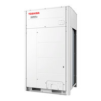
MMY-MUP1201HT8JP
Toshiba MMY-MUP1201HT8JP Manuals
Manuals and User Guides for Toshiba MMY-MUP1201HT8JP. We have
1
Toshiba MMY-MUP1201HT8JP manual available for free PDF download: Service Manual
Toshiba MMY-MUP1201HT8JP Service Manual (310 pages)
AIR CONDITIONER (MULTI TYPE) Super Modular Multi System-u SMMS-u
Brand:
Toshiba
| Category:
Air Conditioner
| Size: 24.74 MB
Table of Contents
Table of Contents
2
Generic Denomination: Air Conditioner
6
Safety Caution
6
Definition of Qualified Installer or Qualified Service Person
6
Definition of Protective Gear
7
Explanation of Illustrated Marks
7
Explanation of Indications
7
Precautions for Safety
8
Explanations Given to User
12
Relocation
12
Cautions on Installation/Service
13
Pipe Materials
13
Safety Caution Concerned to Refrigerant (R410A)
13
Refrigerant (R410A)
13
Required Tools for R410A
14
Tools
14
General Tools
14
Explanation of Symbols
14
Wiring Diagrams
16
Parts Rating
19
Outdoor Unit (50Hz Model: MMY-MUP***1HT8*)
19
Outdoor Unit (60Hz Model: MMY-MUP***1HT7*)
20
Outdoor Unit (50Hz Model: MMY-MUP***1HT8P-A)
21
Winding Resistance of Outdoor Unit Main Parts
22
Inverter Assembly
23
Parts Layout in Outdoor Unit
24
Parts Layout in Inverter Assembly
25
Outdoor (Inverter) Print Circuit Board
28
Interface P.C. Board (MCC-1747)
28
Noise Filter P.C. Board (MCC-1748)
29
Inverter P.C. Board for Compressor (MCC-1729)
30
Inverter P.C. Board for Fan (MCC-1734)
31
USB Isolate P.C. Board (MCC-1754)
32
Refrigerant Piping Schematic Drawing
33
Indoor Unit
37
U Series Indoor Unit Functional Part Explanation
37
Combined Refrigerant Piping System Schematic Diagrams
38
Refrigerant Flow (Cooling)
38
Refrigerant Flow (Single Defrost)
39
Refrigerant Flow (Heating)
40
Refrigerant Flow (Individual Defrost)
41
Follower Unit
41
Header Unit
41
1) Refrigerant Flow (Automatic Emergency Cooling)
42
1) Refrigerant Flow (Automatic Emergency Heating)
44
Refrigerant Flow (Reclaim)
46
5
47
Control Outline
47
Outdoor Unit
47
Cooling Fan Control
48
Heating Fan Control
48
Control Content
50
Control Start Condition
50
During Cooling Operation
50
During Heating Operation
50
Defrost Control Content
51
Defrost End Control Content
51
Defrost Termination Condition
51
Defrosting Start Condition
51
Release Condition
52
SV4 Gas Balance Control
52
SV4 High Pressure Release Control
52
SV4 Low Pressure Release Control
52
Current, Power Release Value Control
54
Heat Sink Overheat Abnormality
54
High Pressure SW Control
54
Cooling Operation at Low Outdoor Temperature
55
Fan Mode During Heating Operation on same System Line of Indoor Unit
55
PMV (Pulse Motor Valve)
55
Adjustment Range
56
Distinction of Outdoor Unit
56
Indoor Unit
56
Air Speed Selection
59
Prevention of Cold Air Discharge
60
Reset Conditions
60
Louver Position Setup
63
Swing Setup
63
Individual Air Direction Setup
64
Louver Lock
65
Selection of Swing Mode
65
Applied Control and Functions
67
Optional Connector Specifications of Indoor P.C.board
67
Test Operation of Indoor Unit
69
How to Operate
69
How to Clear
69
Method to Set Indoor Unit Function DN Code
70
Indoor Unit Function Code No. (DN Code) Table
72
External Static Pressure & High-Ceiling Adjustment
75
Applicable Controls Setup
77
Interface P.C. Board of Header Unit
77
Method to Set Outdoor Unit Function Code No. (O.DN )
77
When Switching from the Wired Remote Controller (RBC-ASCU11*)
78
Basic Procedure
78
Outdoor Unit Function Code No. (O. DN) Table
80
Applied Control of Indoor Unit
82
Control Items
82
Ventilating Fan Control from Remote Controller
83
Operation
83
Wiring
83
Auto-Off Feature Control
84
Connecting to the CN61 Connector
84
Code (DN) Setup
84
Power Peak-Cut from Indoor Unit
85
Applied Control of Outdoor Unit
86
Outdoor Fan High Static Pressure Shift
86
Maximum External Static Pressures of Single Outdoor Units
86
Purpose/Characteristics
86
Priority Operation Mode Setting
87
Indoor Unit Setup Method for Priority Indoor Unit Mode
87
Outdoor Unit Setup Method
87
Applied Control of Outdoor Unit
90
Four-Core Cable Support
91
Power Peak-Cut Control
91
Power Peak-Cut Control Settings
91
Specifications of Display Relay Contact
91
COM Contact Specifications
92
Two-Core Cable Support
92
4-Stage Switching
93
Extended Power Peak-Cut Control Settings
93
Power Peak-Cut Control through Electric Power
94
External Master ON/OFF Control
95
Snowfall Fan Control
95
Night Operation (Sound Reduction) Control
96
Indoor Unit Operation Intervention Function
97
Operation Mode Selection Control
97
Output Relay (K1, K2) Contact Specifications
98
Trouble/Operation Output
98
Compressor Operation Output
99
Operating Rate Output
100
Notice Code
101
Notice Code Mark Display on Wired Remote Controller
101
Notice Code Display (7-Segment Display) Outdoor Interface P.C. Board
102
Notice Code List
102
System Cooperation Defrosting
103
Setup Method
104
Wiring and Setup Examples
104
2-System Setup
104
3-System Setup
104
Operations (Contents of Control)
105
Operation Examples of System Cooperation Defrosting
105
Examples of Not Performing System Cooperation Defrosting
105
2-System Cooperation Defrosting out of Three Systems
105
Night Operation (Sound Reduction Control)
106
Test Operation
108
Procedure and Summary of Test Operation
108
Main Check Items for Electric Wiring
109
Check Items before Test Operation (before Powering-On)
109
Check the Additional Amount of Refrigerant
112
Corrective Amount of Refrigerant According to Indoor Unit Horsepower
113
According to Indoor Unit Horsepower for DX Coil Interface
113
According to Indoor Unit Horsepower for Hot Water Module (HWM)
114
Check at Main Power-On
115
Check on the Outdoor Unit
115
Interface P.C. Board
115
Check on the Indoor Unit
116
Normal Status
116
When Power Is Not Supplied Normally
116
Address Setup and Check Procedure
117
Precautions
117
Address Setup Procedure
118
Header Outdoor Unit Setting
118
Interface P.C. Board on the Header Outdoor Unit
118
Line (System) Address Setting
119
Manual Address Setup from the Remote Controller
124
Confirming the Numbers and Positions of Indoor Units
127
To Find an Indoor Unit’s Position from Its Address
128
When Checking Unit Numbers Controlled as a Group
128
Changing the Indoor Unit Address Using a Remote Controller
129
To Change an Indoor Unit Address Using a Wired Remote Controller
130
Resetting the Address
131
Communication Setting
132
Address Setting
133
Clear the Communication Setting
133
In the Case of an Increase in Address-Undefined Indoor Units
133
Resetting the Communication (Resetting to the Factory Default)
133
Communication Method Setting
134
Check after Address Setup When Central Control System Is Connected
135
Troubleshooting in Test Operation
136
A Check Code Is Displayed on the Remote Controller
136
No Remote Controller Response with Check Code
137
No Remote Controller Response Without Check Code
137
Connected Indoor/Outdoor Unit Quantity Check
138
Miswiring Example
139
Test Operation Check
140
Fan Check
140
Cooling/Heating Test Operation Check
141
Test Operation Start/Stop Operation
141
Wired Remote Controller
141
Cooling Test Run
142
Heating Test Run
142
Wireless Remote Controller
142
Criteria for Cycle Status
144
Criteria for Operating Power Current
144
Criteria for Operating Pressure
144
Service Support Function
145
Check Function for Connecting of Refrigerant and Control Lines
145
On Rotations of Outdoor Fans
146
Function to Start/Stop (ON/OFF) Indoor Unit from Outdoor Unit
147
Cooling Test Operation Function
149
Heating Test Operation Function
150
Fan Test Operation Function
151
Batch Start/Stop (ON/OFF) Function
152
Individual Start/Stop (ON/OFF) Individual Test Operation Function
153
Check Code Clearing Function
154
Check Code Clearing in Indoor Unit
154
Check Code Clearing in Outdoor Unit
154
Clearing from the Main Remote Controller
154
Clearing a Check Code of the Outdoor Unit
155
Clearing Check Code by Resetting Power
156
Remote Controller Distinction Function
157
Pulse Motor Valve (PMV) Forced Open/Close Function in Indoor Unit
158
Control Start Method
159
Method of Operating Solenoid Valve
159
Method to Switch Solenoid Valve/Pmv Display
159
Pulse Motor Valve (PMV) Forced Open/Close Function and Solenoid Valve
159
Forced on Function in Outdoor Unit
159
Cancelation Method
160
Method of Operating Pulse Motor Valve (PMV) (Forced Open/Close)
160
Fan Operation Check in Outdoor Unit
161
Abnormal Outdoor Unit Discrimination Method by Fan Operating Function
162
In Case to Operate the Fan in the Failed Outdoor Unit Only
162
In Case to Operate the Fans in All the Normal Outdoor Units
162
Manual Adjustment Function of Outside Temperature (TO) Sensor
163
Service Support Function List
163
Checking the Record of the Initial Value
164
Clearing the Initial Value
164
Confirming the Refrigerant Leakage
164
Refrigerant Leakage Detection
164
Monitor Function of Remote Controller Switch
165
Switching to the Service Monitor Mode
165
Wave Tool Advance for SMMS-U Series
167
Before the Use of Wave Tool Advance
167
About Wave Tool Advance
167
Valid/Prohibition/Permission Setting for Test Operation from WTA App
167
Confirmation for NFC Tag Communication
168
Before Engaging in Troubleshooting
169
Troubleshooting
169
List of Check Codes (Indoor Unit)
170
Overview
169
Troubleshooting Method
170
Check Code Detected by Central Control Device
171
Check Code Detected by Remote Controller
171
List of Check Codes (Outdoor Unit)
172
How to Read Displayed Information
176
Troubleshooting Based on Information Displayed on Remote Controller
176
Using Main Remote Controller (RBC-ASCU11*)
176
Other (Indications Not Involving Check Code)
179
Check Codes Displayed on Remote Controller and SMMS-U Outdoor Unit (7-Segment Display on I/F Board) and Locations to be Checked
180
Check Codes Detected by Central Control Device
193
How to Check Inverter Output
194
How to Check Outdoor Fan Motor
194
How to Check Resistance of Compressor Winding
194
Points to Note When Servicing Compressor
194
Diagnosis Procedure for each Check Code
195
7-Segment Display Function
226
7-Segment Display on Outdoor Unit (Interface P.C. Board)
226
Checking Procedure to be Followed in Event of Abnormal Shutdown
227
Display of System Information
228
Display of Outdoor Unit Information
229
Display of Outdoor Cycle Data
230
Display of Indoor Unit Information
232
Display of Outdoor EEPROM Writing Check Code
232
Oil Level Judgment Display
233
Oil Level Judgment Results
233
Operation Procedure
233
SMMS-U Outdoor Interface P.C. Board Function Setting Change Table
234
Switch/Function Setting Change
234
Leakage/Clogging of Refrigerating Cycle Circuit
236
Outdoor TD1, TD2, TK1 and TK2 Sensors
242
Outdoor TS1, TS3, TE1, TE2, TE3, TL1, TL2, TL3 and to Sensors
242
Sensor Characteristics
242
Temperature Sensor Characteristics
242
Input/Output Wiring Summary
243
Output Voltage Vs. Pressure
243
Pressure Sensor Characteristics
243
Indoor TC1 Sensor
244
Indoor TC2 and TCJ, TOA Sensor
244
Pd Sensor Characteristics
245
Pressure Sensor Output Check
245
PS Sensor Characteristics
246
Backup Operation (Emergency Operation)
247
Note for Backup Operation
247
Compressor Backup Operation Setting
248
Work Procedure
248
Outdoor Unit Backup Operation Setting
250
Follower Outdoor Unit Backup Operation Setting (Failure of Follower Outdoor Unit)
250
Setup of Failed Follower Outdoor Unit
250
Setup of Header Unit
251
Header Outdoor Unit Backup Operation Setting
253
Selection of New Header Unit
253
Setup of Failed Header Outdoor Unit
253
Unit)
253
Wiring Changes to Communication Line
254
Cooling-Season Outdoor Unit Backup Operation Setting
255
Setup of Failed Outdoor Unit
255
Outdoor Unit Automatic Backup Operation Outline
256
Outdoor Unit Refrigerant Recovery Method
257
Refrigerant Recovery from Troubled Outdoor Unit (Reclaim)
257
Note for Refrigerant Recovery Operation
257
Refrigerant Recovery Procedure a
257
Unit Turn On)
257
Failure Outdoor Unit
258
Does Not Turn On)
259
Refrigerant Recovery Procedure B
259
How to Operate System While Troubled Outdoor Unit Being Repaired
260
Work Procedure after Repair
261
Replacing Compressors
262
Compressor Replacement Procedure (Outline)
262
Checking Color of Oil in Troubled Compressor
263
Replacement of Compressors
263
Adjusting Amount of Oil in New Compressor
264
Measuring Amount of Oil in Troubled Compressor
264
When Replacing Troubled Compressor Only
264
Adjusting Amount of Oil in New Compressors
265
Measuring Amount of Oil in Normal Compressor
265
Remove the Normal Compressor
265
Installing Compressor
266
Method to Fully Open PMV Manually
266
Refrigerant Charging
266
Vacuum-Pumping
266
Check Procedure to Search Cause of Compressor Oil Shortage
267
Attachment
271
Detachment
271
Outdoor Unit Parts Replacement Methods
271
List of Service Parts (Inverter)
285
P.C. Board Replacement Procedures
285
Replacement of Outdoor P.C. Board & Inverter Parts
285
Configuration of Inverter Assembly
286
Included Item
289
Interface P.C. Board (MCC-1747) Replacement Procedure
289
Arrangement of a Switch
290
Compressor P.C. Board (MCC-1729) Replacement Procedure
290
Fan-Motor P.C. Board (MCC-1734) Replacement Procedure
292
Noise Filter P.C. Board 1 (MCC-1748) Replacement Procedure
293
Noise Filter P.C. Board 2 (MCC-1748) Replacement Procedure
294
Exploded Diagram/Parts List
295
Outdoor Unit (8, 10, 12, 14HP)
295
Outdoor Unit (14A, 16, 18, 20HP)
298
Outdoor Unit (22, 24HP)
301
Advertisement
Advertisement
Related Products
Toshiba MMY-MUP1201HT7JP
Toshiba MMY-MUP1201HT8P
Toshiba MMY-MUP1201HT7P
Toshiba MMY-MUP1201HT8P-A
Toshiba SMMS-u MMY-MUP1201HT8
Toshiba MMY-MUP1201HT6P-UL
Toshiba MMY-MUP1201HT9P-UL
Toshiba MMY-MUP1201HT8P-TR
Toshiba MMY-MUP1201HT8JP-TR
Toshiba MMY-MUP1201FT6P-UL
Toshiba Categories
Laptop
Air Conditioner
TV
LCD TV
All in One Printer
More Toshiba Manuals
Login
Sign In
OR
Sign in with Facebook
Sign in with Google
Upload manual
Upload from disk
Upload from URL