Sign In
Upload
Manuals
Brands
Toshiba Manuals
Air Conditioner
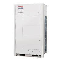
MMY-MUP120H1FT9PUL
Toshiba MMY-MUP120H1FT9PUL Manuals
Manuals and User Guides for Toshiba MMY-MUP120H1FT9PUL. We have
1
Toshiba MMY-MUP120H1FT9PUL manual available for free PDF download: Service Manual
Toshiba MMY-MUP120H1FT9PUL Service Manual (386 pages)
Brand:
Toshiba
| Category:
Air Conditioner
| Size: 59.79 MB
Table of Contents
Table of Contents
2
Safety Caution
6
Refrigerant (R410A)
21
Wiring Diagrams
24
Parts Rating
32
Outdoor Unit (MMY-MUP***1HT6P-UL)
32
Winding Resistance of Outdoor Unit Main Parts
33
Inverter Assembly
35
Flow Selector Unit (Multi-Port , Single-Port)
35
Parts Layout in Outdoor Unit
36
Parts Layout in Inverter Assembly
38
Outdoor (Inverter) Print Circuit Board
45
Interface P.C. Board (MCC-1747)
45
1). Noise Filter P.C. Board (MCC-1749)
46
2). Noise Filter P.C. Board (MCC-1749)
47
1). Inverter P.C. Board for Compressor (MCC-1729)
48
2). Inverter P.C. Board for Compressor (MCC-1729)
49
Capacitor P.C.board (MCC-1711)
50
Inverter P.C. Board for Fan (MCC-1734)
51
USB Isolate P.C.board (MCC-1754)
52
Parts Layout in Flow Selector Unit
53
Parts Layout in Flow Selector Unit Multi-Port Type
53
Parts Layout in Flow Selector Unit Single-Port Type
53
Parts Layout in Electric Part Assembly (Flow Selector Unit)
54
Parts Layout in Flow Selector Unit
55
FS Unit Multi-Port Type P.C. Board (MCC-1770)
55
FS Unit Single-Port Type P.C. Board (MCC-1771)
56
Refrigerant Piping Schematic Drawing
57
Single Defrost Unit
63
Heating Operation (Operation of Heating Only)
64
Individual Defrost Operation
65
Simultaneous Cooling Operation (Operation of Cooling and Heating)
66
Simultaneous Heating Operation (Operation of Cooling and Heating)
67
Emergency Cooling Operation (Operation of Cooling Only)
68
Manual Emergency Heating
69
Control Outline
70
Outdoor Unit
70
Indoor Unit
79
Applied Control and Functions
90
Method to Set Outdoor Unit Function Code No. (O.DN )
90
Applied Control of Outdoor Unit
95
Outdoor Fan High Static Pressure Shift
95
Priority Operation Mode Setting
96
Applied Control of Outdoor Unit
98
Notice Code
110
System Cooperation Defrosting
112
Night Operation (Sound Reduction Control)
115
Test Operation
117
Procedure and Summary of Test Operation
117
Check Items before Test Operation (before Powering-On)
118
Check at Main Power-On
125
Address Setup
127
Precautions
127
Address Setup and Check Procedure
127
Address Setup Procedure
128
Setting When Connecting Indoor Units to FS (Flow Selector)
151
Check after Address Setup When Central Control System Is Connected
152
Troubleshooting in Test Operation
154
A Check Code Is Displayed on the Remote Controller
154
No Remote Controller Response with Check Code
156
No Remote Controller Response Without Check Code
156
Connected Indoor/Outdoor Unit Quantity Check
157
Test Operation (Test Run) Check
163
Fan Check
163
Inspection Mode (Safety Measures)
164
Cooling/Heating Test Operation Check
165
Service Support Function
170
Check Function for Connecting of Refrigerant and Control Lines
170
Function to Start/Stop (ON/OFF) Indoor Unit from Outdoor Unit
172
Check Code Clearing Function
179
Remote Controller Distinction Function
181
Pulse Motor Valve (PMV) Forced Open/Close Function in Indoor Unit
182
Forced on Function in Outdoor Unit
183
Pulse Motor Valve (PMV) Forced Open/Close Function in FS Unit
184
Fan Operation Check in Outdoor Unit
186
Abnormal Outdoor Unit Discrimination Method by Fan Operating Function
187
Manual Adjustment Function of Outside Temperature (TO) Sensor
188
Confirmation of the Check Code ( L02, L11, L13, L14 ) Occurred During
189
Installation
189
Confirmation of the Number of FS Units Connected
189
Refrigerant Leakage Detection
190
Monitor Function of Remote Controller Switch
191
Before the Use of Wave Tool Advance
193
About Wave Tool Advance
193
Valid/Prohibition/Permission Setting for Test Operation from WTA App
193
Confirmation for NFC Tag Communication
194
Troubleshooting
195
Overview
195
Troubleshooting Method
196
Troubleshooting Based on Information Displayed on Remote Controller
202
Check Codes List
206
Diagnosis Procedure for each Check Code
225
7-Segment Display Function
264
Oil Level Judgment Display
271
SMMS-U Outdoor Interface P.C. Board Function Setting Change Table
272
Leakage/Clogging of Refrigerating Cycle Circuit
274
Sensor Characteristics
280
Pressure Sensor Output Check
283
Backup Operation (Emergency Operation)
285
Note for Backup Operation
285
Compressor Backup Operation Setting
286
Outdoor Unit Backup Operation Setting
288
Follower Outdoor Unit Backup Operation Setting
288
Unit)
288
Header Outdoor Unit Backup Operation Setting
291
Unit)
291
Cooling-Season Outdoor Unit Backup Operation Setting
293
Outdoor Unit Refrigerant Recovery Method
294
Refrigerant Recovery from Troubled Outdoor Unit (Reclaim)
294
Note for Refrigerant Recovery Operation
294
Refrigerant Recovery Procedure a
294
Unit Turn On)
294
Refrigerant Recovery Procedure B
296
Does Not Turn On)
296
How to Operate System While Troubled Outdoor Unit Being Repaired
297
Work Procedure after Repair
298
Replacing Compressors
299
Compressor Replacement Procedure (Outline)
299
Replacement of Compressors
300
Check Procedure to Search Cause of Compressor Oil Shortage
304
Outdoor Unit Parts Replacement Methods
308
Board Replacement Procedures
326
Replacement of Outdoor P.C. Board & Inverter Parts
326
List of Service Parts (Inverter)
326
Configuration of Inverter Assembly
328
Interface P.C. Board (MCC-1747) Replacement Procedure
335
1). Compressor P.C. Board (MCC-1729) Replacement Procedure
339
2). Compressor P.C. Board (MCC-1746) Replacement Procedure
341
Capacitor P.C.board (MCC-1711) Replacement Procedure
343
Fan-Motor P.C.board (MCC-1734) Replacement Procedure
345
1). Noise Filter P.C. Board (MCC-1749) Replacement Procedure
346
2). Noise Filter P.C. Board (MCC-1749) Replacement Procedure
347
3). Noise Filter P.C. Board (MCC-1749) Replacement Procedure
348
Fs Unit Parts Replacement Methods
349
Flow Selector Unit Multi-Port Type
349
Flow Selector Unit Single-Port Type
354
Exploded Diagram/Parts List
359
Outdoor Unit
359
Flow Selector Unit Multi-Port Type
384
Flow Selector Unit Single-Port Type
385
Advertisement
Advertisement
Related Products
Toshiba MMY-MUP120H1HT6PUL
Toshiba MMY-MUP120H1HT9PUL
Toshiba MMY-MUP120H1FT6PUL
Toshiba MMY-MUP1201HT8P
Toshiba MMY-MUP1201HT7P
Toshiba SMMS-u MMY-MUP1201HT8
Toshiba MMY-MUP1201HT9P-UL
Toshiba MMY-MUP1201HT8P-TR
Toshiba MMY-MUP1201FT9P-UL
Toshiba MMY-MUP1201T8JP
Toshiba Categories
Laptop
Air Conditioner
TV
LCD TV
All in One Printer
More Toshiba Manuals
Login
Sign In
OR
Sign in with Facebook
Sign in with Google
Upload manual
Upload from disk
Upload from URL