Sign In
Upload
Manuals
Brands
Toshiba Manuals
Air Conditioner
RAV-SM407KRTP-E
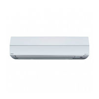
User Manuals: Toshiba RAV-SM407KRTP-E Air Conditioner
Manuals and User Guides for Toshiba RAV-SM407KRTP-E Air Conditioner. We have
2
Toshiba RAV-SM407KRTP-E Air Conditioner manuals available for free PDF download: Service Manual, Installation Manual
Toshiba RAV-SM407KRTP-E Service Manual (113 pages)
Air Conditioner Split Type
Brand:
Toshiba
| Category:
Air Conditioner
| Size: 3.54 MB
Table of Contents
Service Manual
1
Table of Contents
2
Definition of Qualified Installer or Qualified Service Person
3
Generic Denomination: Air Conditioner
3
Original Instruction
3
Safety Caution
3
Definition of Protective Gear
4
Explanation of Illustrated Marks
4
Explanation of Indications
4
Confirmation of Warning Label on the Main Unit
5
Warning Indications on the Air Conditioner Unit
5
Precautions for Safety
6
Explanations Given to User
10
Relocation
10
Declaration of Conformity
11
Specifications
11
1 Specifications
12
High Wall Type
12
4-Way Air Discharge Cassette Type
13
2 Construction Views (External Views)
13
3 Systematic Refrigerating Cycle Diagram
15
4 Wiring Diagram
16
Name of each Part
17
5 Specifications of Electrical Parts
17
6 Refrigerant R410A
18
Safety During Installation/Servicing
18
Refrigerant Piping Installation
18
Piping Materials and Joints Used
18
Thicknesses of Annealed Copper Pipes
19
Minimum Thicknesses of Socket Joints
19
Processing of Piping Materials
19
Flare Processing Procedures and Precautions
19
Dimensions Related to Flare Processing for R410A
20
Flare Processing Dimensions
20
Flare Processing
20
Dimensions Related to Flare Processing for R22
20
Flare and Flare Nut Dimensions for R22
21
Relations between Flare Nut and Flare Seal Surface
21
Flare Connecting Procedures and Precautions
21
Tightening Torque of Flare for R410A
21
Required Tools
22
Tools Exclusive for R410A
22
General Tools
22
Recharging of Refrigerant
23
Configuration of Refrigerant Charging
23
Brazing of Pipes
24
Materials for Brazing
24
Silver Brazing Filler
24
Flux
24
Brazing
25
Characteristics Required for Flux
25
Types of Flux
25
Brazing Method to Prevent Oxidation
25
Indoor Unit Control
26
Indoor Controller Block Diagram
26
Connection of Wired Remote Controller
26
7 Indoor Control Circuit
26
Connection of Wireless Remote Controller
27
Control Specifications (High Wall Type)
28
Fan Speed Control
30
Cool Air Discharge Preventive Control
31
Freeze Preventive Control
32
High-Temp. Release Control
32
Auto Restart
36
Save Operation
36
Self-Clean Operation
36
Hi POWER
37
Comfort Sleep
38
Cooling Operation
38
Heating Operation
38
PRESET Operation
39
QUIET Operation
39
SLEEP Operation
39
Indoor Print Circuit Board (High Wall Type)
40
High Wall Type P.C. Board Optional Switch/Connector Specifications
41
Required Tools/Instruments
42
Summary of Troubleshooting
42
Confirmation Points before Check
43
Outline of Judgment
43
Troubleshooting Procedure
43
Troubleshooting
44
Error Mode Detected by Indoor Unit
48
Error Mode Detected by Remote Controller or Central Controller (Tcc-Link)
49
Error Mode Detected by Outdoor Unit
50
Check Code
52
Diagnostic Procedure for each Check Code
52
E01 Error
52
E09 Error
52
E04 Error
53
E10 Error
53
E08, L03, L07, L08 Error
54
E18 Error
54
L09 Error
54
F10 Error
56
L30 Error
56
P12 Error
57
F01 Error
58
F02 Error
58
F29 Error
58
P31 Error
58
Temperature Sensor
59
Temperature – Resistance Value Characteristic Table
59
9 Replacement of Service P.C. Board
60
Requirement When Replacing the Service Indoor P.C. Board Assembly
60
Minimum Requirements for CODE No.
61
Readout of the Setup Data from EEPRO
61
H2 Replacement of Service P.C. Board
62
Method of DIP Switch Setting
63
P.C. Board Parts Layout Drawing
63
Writing of the Setup Contents to EEPROM
64
CODE No. (DN) Table (Please Record the Objective Unit Data at Field)
65
Indoor Unit Capacity (CODE No. [11])
65
Checking Wiring and Piping of Indoor/Outdoor Units
66
10 Setup at Local Site and Others
66
Test Run Setup on Remote Controller
66
Wired Remote Controller
66
D02 (Red)
67
Forced Defrost Setup of Remote Controller
67
LED Display on P.C. Board
67
Preparation in Advance
67
Function Selection Setup
68
Function Selection CODE No. (DN) List
69
2-Remote Controller Control
70
Wireless Remote Controller A-B Selection
70
Wiring and Setting of Remote Controller Control
70
Calling of Sensor Temperature Display
71
Monitor Function of Remote Controller Switch
71
Address Setup
72
Calling of Error History
72
Display Range on Remote Controller
72
Group Control Operation
72
Indoor Unit Power-ON Sequence
73
Usual Regular Communication
73
Connection Diagram
74
TCC-LINK Central Control
74
Central Control for Custom Indoor Units Only
75
Wiring Specifications
75
Setting Onboard Switches
76
Onboard Switch Setting Procedure
77
Setting Addresses
79
Manual Setting/Change of Indoor Unit Refrigerant Line Addresses
80
Central Control Address Number Setting
82
Setting by Remote Controller on Indoor Unit Side
82
Address Setting
83
Address Setup Procedure
83
Address Setting and Group/Twin/Triple Control
84
System Configuration
84
Examples of Aut Address Setting Fro no Address Setting
85
Multiple Group Operation
85
Address Setting
86
Checking Location of Indoor Unit Number
87
To Find the Address of Indoor Unit Whose Location Is Clear
87
To Find the Location of Indoor Unit from Its Address
87
12 Detachments
88
Evaporator
91
Bearing
92
Fan Motor
93
Cross Flow Fan
94
13 Exploded Views and Parts List
95
Electric Parts
96
14 APPENDIX (Lite-Vision Plus Remote Controller Installation Manual)
97
Accessory Parts
98
Installation
99
Installation Dimension
99
Installation Place
99
Remote Control Wiring and Inter-Unit Wiring
99
Install the Remote Controller
100
Requirements for Wiring
100
Wire the Remote Controller
100
Basic Wiring Diagram
101
For First Use
101
To Diverge from the Header Remote Controller
101
To Diverge from the Indoor Unit
101
Detailed Display Mode
102
Monitor Screen
102
Part Names and Functions
102
Name of Room
103
To Adjust the Clock
103
Backlight
104
Key Lock
104
Screen Contrast
104
Header/Follower
105
Language
105
Field Setting Menu
106
Performing the Test Mode
106
Test Mode
106
Register Service Info
107
Entering Information Manually
108
Entering the Contact Number for Service
108
Alarm History
109
DN Setting
110
Monitor Function
110
Check of Concentration Limit
111
Warnings on Refrigerant Leakage
111
Advertisement
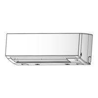
Toshiba RAV-SM407KRTP-E Installation Manual (24 pages)
SPLIT TYPE High Wall Type Indoor Unit
Brand:
Toshiba
| Category:
Air Conditioner
| Size: 2.19 MB
Table of Contents
Installation Manual
1
Table of Contents
2
Warning Indications on the Air Conditioner Unit
3
Precautions for Safety
4
Accessory Parts
5
Installation Diagram of Indoor and Outdoor Units
6
Installation Space
6
Selection of Installation Place
6
Wireless Remote Controller
7
Installation
7
Cutting a Hole and Mounting Installation Plate
7
Piping and Drain Hose Installation
8
Indoor Unit Fixing
9
Drainage
9
Refrigerant Piping
9
Electrical Connection
11
Wiring Connection
12
Wiring Diagram
13
Applicable Controls
13
Power Saving Mode
14
Group Control
15
Test Run
20
Periodic Maintenance
21
Maintenance
21
Troubleshooting
22
Advertisement
Related Products
Toshiba RAV-SM407KRTP-A
Toshiba RAV-SM407KRTP-TR
Toshiba RAV-SM407MUT-E
Toshiba RAV-SM407MUT-TR
Toshiba RAV-SM407CTP-E
Toshiba RAV-SM402MUT-E
Toshiba RAV-SM406BT-TR
Toshiba RAV-SM406BTP-E
Toshiba RAV-SM404MUT-E RAV-SM404MUT-TR
Toshiba RAV-SM404ATJP-E
Toshiba Categories
Laptop
Air Conditioner
TV
LCD TV
All in One Printer
More Toshiba Manuals
Login
Sign In
OR
Sign in with Facebook
Sign in with Google
Upload manual
Upload from disk
Upload from URL