Sign In
Upload
Manuals
Brands
Toshiba Manuals
Air Conditioner
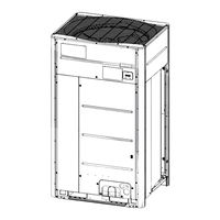
SHRM ADVANCE MMY-SUG2201MT8P-A
Toshiba SHRM ADVANCE MMY-SUG2201MT8P-A Manuals
Manuals and User Guides for Toshiba SHRM ADVANCE MMY-SUG2201MT8P-A. We have
1
Toshiba SHRM ADVANCE MMY-SUG2201MT8P-A manual available for free PDF download: Service Manual
Toshiba SHRM ADVANCE MMY-SUG2201MT8P-A Service Manual (453 pages)
Super Heat Recovery Multi System
Brand:
Toshiba
| Category:
Air Conditioner
| Size: 49.74 MB
Table of Contents
Table of Contents
2
Safety Caution
6
About Refrigerant R32
23
Wiring Diagrams
40
Parts Rating
47
Outdoor Unit (50Hz Model: MMY-SUG***1MT8*)
47
Winding Resistance of Outdoor Unit Main Parts
48
Inverter Assembly
49
Flow Selector Unit (Multi-Port , Single-Port) / Shut-Off Valve Unit
50
Battery Kit
50
Leak Detector
50
Parts Layout in Outdoor Unit
51
Parts Layout in Inverter Assembly
52
Outdoor (Inverter) Print Circuit Board
55
Interface P.C. Board (MCC-1747)
55
Noise Filter P.C. Board (MCC-1748)
56
Inverter P.C. Board for Compressor (MCC-1729)
57
Inverter P.C. Board for Fan (MCC-1734)
58
USB Isolate P.C. Board (MCC-1754)
59
Parts Layout in Flow Selector Unit, Shut-Off Valve Unit, Battery Kit and Leak Detector
60
Parts Layout in Electric Part Assembly (Flow Selector Unit, Shut-Off Valve Unit)
63
Print Circuit Board
64
Flow Selector Unit Multi Type P.C. Board (MCC-1770)
64
Flow Selector Unit Single Type & Shut-Off P.C. Board (MCC-1771)
65
Shut-Off 24HP P.C.board (MCC-1771)
66
Battery Kit P.C.board (MCC-1772)
67
Leak Detector P.C.board (MCC-1782)
68
Refrigerant Piping Schematic Drawing
69
Combined Refrigerant Piping System Schematic Diagrams
75
Defrost Mode (Heat Pump)
76
All Heating Mode (Heat Pump)
77
All Cooling Mode (Heat Recovery)
78
Defrost Mode (Heat Recovery)
79
All Heating Mode (Heat Recovery)
80
Simultaneous Cooling Mode (Heat Recovery)
81
Simultaneous Heating Mode (Heat Recovery)
82
Control Outline
83
Outdoor Unit
83
Indoor Unit
92
Applied Control and Functions
107
Method to Set Outdoor Unit Function Code No. (O.DN )
107
Applied Control of Outdoor Unit
112
Outdoor Fan High Static Pressure Shift
112
Priority Operation Mode Setting
113
Applied Control of Outdoor Unit
116
Notice Code
127
System Cooperation Defrosting
129
Night Operation (Sound Reduction Control)
132
Test Operation
134
Procedure and Summary of Test Operation
134
Check Items before Test Operation (before Powering-On)
135
Check at Main Power-On
142
Address Setup
144
Precautions
144
Address Setup and Check Procedure
144
Address Setup Procedure
145
Check after Address Setup When Central Control System Is Connected
169
Setting When Connecting Indoor Units to FS (Flow Selector)
170
Unit or Shut-Off Valve Unit, and When Connecting Safety Equipment
170
Troubleshooting in Test Operation
229
A Check Code Is Displayed on the Remote Controller
229
No Remote Controller Response with Check Code
231
No Remote Controller Response Without Check Code
231
Connected Indoor/Outdoor Unit Quantity Check
232
Test Operation (Test Run) Check
234
Fan Check
234
Inspection Mode (Safety Measures)
235
Cooling/Heating Test Operation Check
237
FS Unit and Shut-Off Valve Unit Piping Connection,Wiring Connection Check
241
Pump-Down Test Operation
242
Service Support Function
243
Check Function for Connecting of Refrigerant and Control Lines
243
Function to Start/Stop (ON/OFF) Indoor Unit from Outdoor Unit
245
Check Code Clearing Function
252
Remote Controller Distinction Function
254
Pulse Motor Valve (PMV) Forced Open/Close Function in Indoor Unit
255
Pulse Motor Valve (PMV) Forced Open/Close Function and Solenoid Valve
256
Forced on Function in Outdoor Unit
256
Pulse Motor Valve (PMV) Forced Open/Close Function
258
In FS Unit and Shut-Off Valve Unit
258
Fan Operation Check in Outdoor Unit
259
Abnormal Outdoor Unit Discrimination Method by Fan Operating Function
260
Manual Adjustment Function of Outside Temperature (TO) Sensor
261
Confirmation of the Check Code ( L02, L11, L13, L14 )
262
Occurred During Installation
262
Confirmation of the Number of FS Units or Shut-Off Valve Units Connected
263
Refrigerant Leakage Detection
264
Monitor Function of Remote Controller Switch
265
Wave Tool Advance
267
Before the Use of Wave Tool Advance
267
About Wave Tool Advance
267
Valid/Prohibition/Permission Setting for Test Operation from WTA App
267
Confirmation for NFC Tag Communication
268
Troubleshooting
269
Overview
269
Troubleshooting Method
270
Troubleshooting Based on Information Displayed on Remote Controller
278
Check Codes List
282
Diagnosis Procedure for each Check Code
301
7-Segment Display Function
346
Oil Level Judgment Display
352
SHRM-A Outdoor Interface P.C. Board Function Setting Change Table
353
Sensor Characteristics
359
Pressure Sensor Output Check
362
System Operation When the Leak Detector Detects Refrigerant Leak
364
Backup Operation (Emergency Operation)
365
Compressor Backup Operation Setting
365
Outdoor Unit Repairing Method
367
Recovering Refrigerant
367
Repairing
367
Airtightness Test
367
Vacuum Drying
370
Charging Refrigerant
371
Replacing Compressors
373
Compressor Replacement Procedure (Outline)
373
Replacement of Compressors
374
Check Procedure to Search Cause of Compressor Oil Shortage
378
Outdoor Unit Parts Replacement Methods
382
Cabinet
382
Propeller Fan and Fan Motor
383
Heat Exchanger
384
Inverter Assembly
386
Water Proof Cover Assembly
388
Reactor Assembly
389
Compressor
391
4-Way Valve
393
Accumulator
397
Rubber
399
Board Replacement Procedures
400
Replacement of Outdoor P.C. Board & Inverter Parts
400
List of Service Parts (Inverter)
400
Configuration of Inverter Assembly
401
Interface P.C. Board (MCC-1747) Replacement Procedure
404
Compressor P.C. Board (MCC-1729) Replacement Procedure
408
Fan-Motor P.C. Board (MCC-1734) Replacement Procedure
410
Noise Filter P.C. Board 1 (MCC-1748) Replacement Procedure
411
Noise Filter P.C. Board 2 (MCC-1748) Replacement Procedure
412
Fs Unit Parts Replacement Methods
413
FS Unit Multi-Port Type Including Battery Kit
413
FS Unit Single-Port Type Including Battery Kit
420
Shut-Off Valve Unit Including Battery Kit
427
Disposal Method for Battery Kit
435
Leak Detector
436
Exploded Diagram/Parts List
438
FS Unit Single-Port Type
450
Shut off Valve Unit
451
Leak Detector
452
Advertisement
Advertisement
Related Products
Toshiba MMY-SUG2001MT8P-E
Toshiba MMY-SUG2201MT8P-E
Toshiba MMY-SUG2401MT8P-E
Toshiba MMY-SUG2001MT8JP-E
Toshiba MMY-SUG2201MT8JP-E
Toshiba MMY-SUG2401MT8JP-E
Toshiba SHRM ADVANCE MMY-SUG2001MT8P-A
Toshiba SHRM ADVANCE MMY-SUG2401MT8P-A
Toshiba MMY-SUG1201MT8JP-E
Toshiba SHRM ADVANCE MMY-SUG1601MT8P-A
Toshiba Categories
Laptop
Air Conditioner
TV
LCD TV
All in One Printer
More Toshiba Manuals
Login
Sign In
OR
Sign in with Facebook
Sign in with Google
Upload manual
Upload from disk
Upload from URL