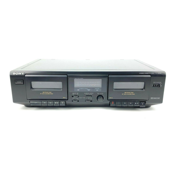
Sony TC-WE305 Service Manual
Hide thumbs
Also See for TC-WE305:
- Operating instructions manual (34 pages) ,
- Service manual (35 pages) ,
- Operating instructions manual (8 pages)
Summary of Contents for Sony TC-WE305
- Page 1 TC-WE305 SERVICE MANUAL Ver 1.2 2003.12 With SUPPLEMENT-1 (9-960-691-81) STEREO CASSETTE DECK Sony Corporation 9-960-691-13 Home Audio Company 2003L02-1 Published by Sony Engineering Corporation © 2003.12...
- Page 13 TC-WE305 Ver 1.1 2002.10 – 18 –...
- Page 21 TC-WE305 US Model Canadian Model SERVICE MANUAL AEP Model E Model Australian Model Ver 1.2 2003.12 PX Model SUPPLEMENT - 1 File this Supplement with the Service Manual. Subject : SUFFIX CHANGE OF THE MAIN, SW AND METER BOARD (ECN-TCA00478)
- Page 22 TC-WE305 CHANGE OF MAIN BOARD The main, SW and meter boards of US, AEP, Australian and E model were changed (CND, SP and PX model are not changed). Printed wiring board and schematic diagram of new type, and changed parts list are described in this Supplement-1.
- Page 23 TC-WE305 DIAGRAMS PRINTED WIRING BOARDS –MAIN Section– LINE • Semiconductor METER Location BOARD (Page 6) Ref. No. Location MAIN BOARD D501 US,AUS,E D502 D503 D504 US,AUS,E D505 D506 D507 D508 BOARD D509 (Page 6) D510 Q701 D511 D701 B-10 D702...
- Page 24 TC-WE305 SCHEMATIC DIAGRAM – MAIN SECTION (1/2) –...
- Page 25 TC-WE305 SCHEMATIC DIAGRAM – MAIN SECTION (2/2) –...
- Page 26 TC-WE305 PRINTED WIRING BOARDS –SW, METER Section– BOARD MAIN MAIN MAIN BOARD (Page 3 ) BOARD BOARD (Page 3 ) (Page 3 ) METER BOARD S702 T701 POWER TRANSFORMER POWER CNP1 AC IN C903 PEAK LEVEL METER * NOT REPLACEABLE:...
- Page 27 TC-WE305 SCHEMATIC DIAGRAM –SW, METER Section–...
- Page 28 TC-WE305 For schematic diagrams. Note on Printed Wiring Boards: Waveforms Note: Note: • X : parts extracted from the component side. • All capacitors are in µF unless otherwise noted. pF: µµF 50 WV or • : internal component. less are not indicated except for electrolytics and tantalums.
-
Page 29: Electrical Parts List
TC-WE305 ELECTRICAL PARTS LIST MAIN METER NOTE : The components identified by mark 0 • Due to standardization, replacements in the • SEMICONDUCTORS or dotted line with mark 0 are critical In each case, u : µ , for example : parts list may be different from the parts for safety. - Page 30 TC-WE305 MAIN METER Ref. No. Part No. Description Remark Ref. No. Part No. Description Remark C520 1-126-964-11 ELECT 10uF D704 8-719-024-99 DIODE 11ES2-NTA2B D705 8-719-933-43 DIODE HZS7A1LTA C521 1-126-963-11 ELECT 4.7uF D706 8-719-991-33 DIODE 1SS133T-72 C522 1-126-964-11 ELECT 10uF D711...
- Page 31 TC-WE305 MAIN METER Ref. No. Part No. Description Remark Ref. No. Part No. Description Remark Q202 8-729-119-78 TRANSISTOR 2SC2785TP-HFE R204 1-247-881-00 CARBON 120K 1/4W R205 1-247-889-00 CARBON 270K 1/4W Q203 8-729-119-78 TRANSISTOR 2SC2785TP-HFE R206 1-247-807-31 CARBON 1/4W Q501 8-729-900-65 TRANSISTOR BN1L4M-TP...
- Page 32 TC-WE305 MAIN METER Ref. No. Part No. Description Remark R531 1-249-429-11 CARBON 1/4W R532 1-249-417-11 CARBON 1/4W F R533 1-249-429-11 CARBON 1/4W R534 1-249-417-11 CARBON 1/4W F R535 1-249-425-11 CARBON 4.7K 1/4W F R536 1-249-425-11 CARBON 4.7K 1/4W F R701 1-249-421-11 CARBON 2.2K...
- Page 33 TC-WE305 MEMO...
- Page 34 TC-WE305 REVISION HISTORY Clicking the version allows you to jump to the revised page. Also, clicking the version at the upper right on the revised page allows you to jump to the next revised page. Ver. Date Description of Revision 1996.05...


