Advertisement
Quick Links
Advertisement

Summary of Contents for Honeywell SLATE R8001S1051
- Page 1 SLATE ™ UV Shutter-Check Flame Amplifier R8001S1051 INSTALLATION INSTRUCTIONS...
- Page 2 Scan for more information...
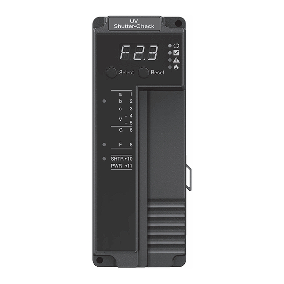
- Page 3 Application SLATE™ brings configurable safety and programmable logic together into one single platform. The platform can easily be customized for almost any requirement or application—offering virtually limitless development opportunities with far less complexity. The R8001S1051 UV Shutter-Check module responds to an ultraviolet signal from an ultraviolet type flame detector to indicate the presence of flame.
- Page 4 Approvals Underwriters Laboratories Inc. Listed, File: MP268 IRI Acceptable Federal Communications Commission: Part 15, Class A Must be mounted inside a grounded metal enclosure. Mounting DIN Rail (See ) Required Components R8001A1001 SLATE Base Controller R8001S9001 SLATE Sub-Base Module 7-3/32 (181) 2-11/16 (68) 4-19/32 (117)
- Page 5 LED Array There are four LEDs on the front of the Shutter-Check Flame Amp module that provide quick identification of the system status and any problems that might occur. The status is broadcast to other modules on the platform bus in case they are affected by the inoperable modules.
- Page 6 Select and Reset Buttons The SLATE system modules have Select and Reset buttons located on the front of the module and beneath the segment display. The Select button is used to scroll through the segment display information. Selector Switch The SLATE Burner Control Module is designed to operate with only one Flame Amplifier Module.
- Page 7 WARNING Electrical Shock Hazard. Can cause severe injury, death or equipment damage. 1. Disconnect the power supply before beginning installation to prevent electrical shock and equipment damage. More than one power supply disconnect can be involved. 2. Verify the Selector Switch is set to 1. See Fig. 2. ROTARY SWITCH MUST BE IN...
- Page 8 M35383 Fig. 3. Installing the UV Shutter-Check Flame Amplifier on the Sub-Base Module. IMPORTANT 1. Wiring must comply with all applicable codes, ordinances and regulations. 2. Wiring must comply with NEC Class 1 (Line Voltage) wiring. 3. The R8001S1051 should not interfere with the propersafety operation of the controls, limits and interlocks it is monitoring.
- Page 9 CAUTION Equipment Damage Hazard. Incorrect combination of relay module, amplifier and flame detector can cause equipment damage. Installing the Flame Detector Proper flame detector installation is the basis of a safe and reliable flame safeguard installation. Refer to the instructions packed with the flame detector and the equipment manufacturer instructions.
- Page 10 Wiring 1. Refer to Fig. 4 for proper flame detector wiring. 2. Disconnect power supply before making wiring connections to prevent electrical shock and equipment damage. UV FLAME AMP WITH SHUTTER-CHECK MODULE REMOTE 4 V+ 5 V– FLAME SIGNAL INPUT/OUTPUT 10 SHTR SHUTTER DRIVE...
- Page 11 3. All wiring must comply with appropriate electrical codes, ordinances and regulations including NEC Class 1 (Line Voltage) wiring where required. 4. Use recommended wire size and type no. 18 copper conductors TTW (60C) or THW (75C) or THNN (90C). 5.
- Page 12 Checkout Preliminary Inspection Make certain that: 1. Wiring connections are correct and all terminal screws and electrical connections are tight. 2. Proper flame failure response time is selected. 3. Amplifier is securely mounted on the DIN Rail and bus connector secured to SLATE Burner Control Module. 4.
- Page 13 a. Add a heat block to stop conducted heat traveling up the sight pipe. b. Add a shield or screen to reflect radiated heat. c. Add cooling (refer to sight pipe ventilation in the detector Instructions). 5. Make sure that the flame adjustment is not too lean. 6.
- Page 14 32-00020—01...
- Page 15 SLATE UV SHUTTER-CHECK FLAME AMPLIFIER ™ R8001S1051...
- Page 16 32-00020-01 For more information and detailed instructions on the R8001S1051 and the entire SLATE system please refer to the SLATE User Guide located on our website at http://combustion.honeywell.com/SLATE Automation and Control Solutions Honeywell International Inc. ® U.S. Registered Trademark. 1985 Douglas Drive North ©...


