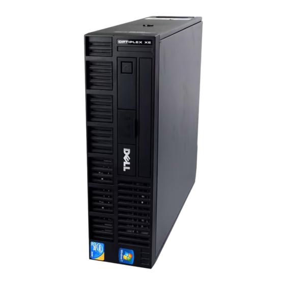
Dell OptiPlex XE Installing Manual
Installing your dell™ optiplex™ xe in an ingress protection 51 (ip51) kit
Hide thumbs
Also See for OptiPlex XE:
- Service manual (43 pages) ,
- Setup & features manual (8 pages) ,
- Configuration (6 pages)
Advertisement
Quick Links
Download this manual
See also:
Service Manual
About Warnings
WARNING:
or death.
Installing Your Dell™ OptiPlex™ XE in an
Ingress Protection 51 (IP51) Kit
WARNING:
shipped with your computer. For additional safety best practices information, see the
Regulatory Compliance Homepage at www.dell.com/regulatory_compliance.
CAUTION:
A minimum space of 10.2 cm (4 inches) is required in the front and back
of the computer to ensure proper ventilation.
CAUTION:
To avoid overheating, it is recommended to maintain an ambient
temperature of less than 40 °C (104 °F) when you use the computer with the IP51 kit.
NOTE:
You need a PCI card slot to install the PCI card-slot filler that ships with the
IP51 kit. You must install the PCI card-slot filler in order to correctly route the fan
power-cable connector from the IP51 kit.
NOTE:
When the computer is installed in the IP51 kit, you will not have access to the
two USB connectors at the front of the computer and the optical drive. You will still have
access to the external power-button connector.
NOTE:
For more information on removing and replacing parts in your computer, see the
Service Manual on the Dell Support website at support.dell.com/manuals.
February 2010
A WARNING indicates a potential for property damage, personal injury,
Before working inside your computer, read the safety information that
Advertisement

Summary of Contents for Dell OptiPlex XE
- Page 1 USB connectors at the front of the computer and the optical drive. You will still have access to the external power-button connector. NOTE: For more information on removing and replacing parts in your computer, see the Service Manual on the Dell Support website at support.dell.com/manuals. February 2010...
- Page 2 1 Open the computer cover. cover-release latch computer cover 2 Open the PCI-card retention clip and remove any unused PCI card-slot filler panel. PCI-card retention clip PCI card-slot filler panel...
- Page 3 3 Install the PCI card-slot filler (shipped with the IP51 kit) into the empty PCI card slot. fan power cable PCI card-slot filler 4 Connect the fan power-cable connector on the PCI card-slot filler to a 4-pin power connector. 5 Replace the computer cover.
- Page 4 6 Remove the front-panel and back-panel screws from the IP51 kit. front panel IP51 kit back panel 7 Open the front and back panels.
- Page 5 8 Remove the screws and open the top cover. 9 Loosen the screw and remove the cable cover. cable cover...
- Page 6 10 Place the computer into the IP51 kit. 11 Fix the screws (supplied with IP51 kit) on the sides of the IP51 kit.
- Page 7 12 Connect the fan cable on the IP51 kit to the computer. 13 Connect the necessary cables to the back of the computer and arrange them in the slots provided on the IP51 kit. 14 Connect the external power-button connector to the front of the computer. external power-button connector...
- Page 8 15 Replace the cable cover. 16 Replace the top cover and replace the screws.
- Page 9 17 Close the front and back panels of the IP51 kit. 18 Replace the front- and back-panel screws.
- Page 10 Information in this document is subject to change without notice. © 2010 Dell Inc. All rights reserved. Reproduction of these materials in any manner whatsoever without the written permission of Dell Inc. is strictly forbidden. Trademarks used in this text: Dell, the DELL logo, and OptiPlex are trademarks of Dell Inc.


