Sign In
Upload
Manuals
Brands
Honeywell Manuals
Transmitter
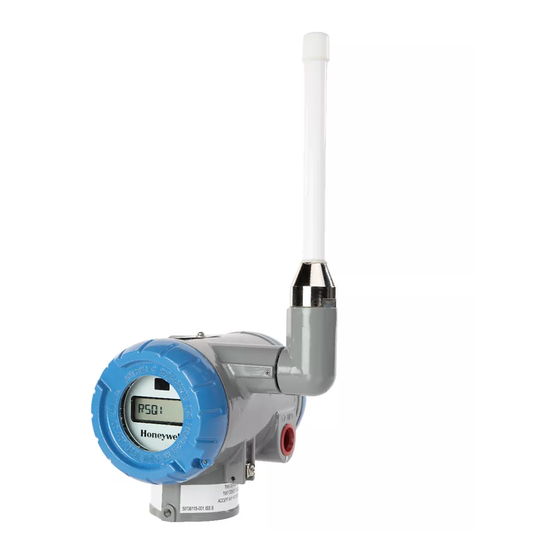
SmartLine STIW400
Honeywell SmartLine STIW400 Manuals
Manuals and User Guides for Honeywell SmartLine STIW400. We have
1
Honeywell SmartLine STIW400 manual available for free PDF download: User Manual
Honeywell SmartLine STIW400 User Manual (106 pages)
Wireless Temperature and Universal I/O Transmitters
Brand:
Honeywell
| Category:
Transmitter
| Size: 4.95 MB
Table of Contents
Table of Contents
7
1 Introduction
13
Purpose
13
Scope
13
Onewireless Network Overview
13
Security Considerations
13
About the Transmitter
15
Figure 1-1 - Smartline Wireless Transmitter Functional Diagram
16
Physical Characteristics
17
Figure 1-2 - Smartline Wireless Transmitter Major Assembly
17
Figure 1-3- Smartline Wireless Transmitter Electronics Housing Components
18
2 Preparation and Quick Start
19
Introduction
19
Set up the Network
19
Transmitter Quick Start
19
3 Installation
21
3.1 Installation Site Evaluation
21
Environmental Conditions
21
Transmitter Weights and Dimensions
22
Table 3-1: Weights
22
Figure 3-1: Temperature/Uio Transmitter Dimensions' Unit MM/Inch
23
Figure 3-2: Temperature/Uio Antenna Dimensions Unit MM/Inch
24
Installation Drawing Number Tables
25
Table 3-2: Drawing Numbers for Temperature/Uio Transmitters
25
Conduit / Cable Entries
26
Summary
26
Table 3-3: Conduit Entry Plugs and Cable Glands for Your Transmitter
26
Mounting Summary
27
Figure 3-3: Typical Flat Bracket Mounted
27
Figure 3-4: Typical Angle Bracket Mounted
28
Figure 3-5: Pipe Mounting Bracket Secured to a Horizontal or Vertical Pipe
29
Rotate Transmitter Housing
30
Figure 3-6: Rotating Transmitter Housing
30
Rotate Display
31
Tools Required
31
Procedure
31
Display Adjustment
31
Figure 3-7: Display Rotation
32
Antenna Adjustment and Mounting
33
Requirements
33
Integral Antenna
33
Figure 3-8: Elbow Antenna Adjustment
34
3.10 Remote Antenna
35
Outdoor Installation Warnings
35
Choosing a Mounting Location
36
Site Selection
36
Mounting the Antenna
37
Directional Mounting Procedure
38
Omnidirectional Mounting Procedure
39
Figure 3-9: Directional Antenna Mounting
39
Grounding the Antenna
40
Figure 3-10: Omnidirectional Antenna Mounting
40
4 Sensor and Electrical Connections
42
Introduction
42
I/O Types
42
STIW400 Terminal Connections
43
Figure 4-1: STIW400 Terminal Connections
43
STUW750 Terminal Connections
44
Figure 4-2: STUW750 Terminal Connections
44
STUW751 Terminal Connections
45
Figure 4-3: STUW751 Terminal Connections
45
5 Power and Start up
46
Battery Power Option
46
Install/Replace Batteries
46
Figure 5-1: IS Battery Pack Installation
47
Figure 5-2: IS Battery Pack
47
Battery Pack Installation and Replacement Procedure
48
Battery Pack Test Terminals
48
Power Supply Option
49
Figure 5-3: 24V Power Supply Installation
49
24V Power Supply
50
Figure 5-4: 24V Power Supply Module
50
24V Power Supply Connection/Replacement Procedure
51
Grounding
52
24V DC Power Supply Option (DC) System Diagram
52
Figure 5-5: Power Supply 24V DC Option (DC) System Diagram
52
Display Sequence
53
Provisioning
53
6 Function Blocks
54
Introduction
54
Block Description
54
Block Types
54
Table 6-1: Blocks
54
7 Operation
55
Transmitter Connection Status
55
Table 7-1: Transmitter Connection Status
55
Transmitter PV Display
57
Table 7-2: Transmitter PV Display
57
PV Status
58
Table 7-3: PV Status
58
Table 7-4: Device Status
59
Table 7-5: Smartline TEMP-UIO Units
61
Table 7-6: Radio Menu
61
Transmitter Channel Configuration
62
Channel Status
62
Channel Configuration
62
Cold Junction
63
Digital Inputs
63
Provisioning Device Menus
64
Overview
64
Main Menu
64
Security and Node Deployment
64
Figure 7-1: Main Menu
64
Figure 7-2: Security and Node Deployment
65
De-Provisioning
66
Read Device Information
66
Figure 7-3: Read Device Information
66
Table 7-7: Read Device Information
67
Advanced Options
68
Figure 7-4: Advanced Options
68
Calibrating the Transmitter
69
Overview
69
Zero Calibration
69
Table 7-8: Advanced Options
69
Two Point Calibration
70
Clearing Calibration
70
8 Maintenance/Repair
71
Introduction
71
Transmitter Firmware Upgrade
71
Preventive Maintenance
71
Replacing Electronics Module
72
Tools Required
72
Procedure
72
Table 8-1: Electronics Module Replacement
72
Replacing Batteries
73
When to Replace
73
Replacing 24V External Power Module
73
Figure 8-1: Electronics Module Removal and Replacement
73
Replacing Antenna
74
Tools Required
74
Procedure
74
Antenna Replacement Procedure
75
Figure 8-2: Antenna Replacement
76
9 Parts
77
Transmitter Body
77
Table 9-1: Transmitter Body Parts
77
Figure 9-1: Angle and Flat Bracket Parts
78
Mounting Brackets
78
Table 9-2: Angle and Flat Bracket Parts (Refer to Figure 9-1)
79
Table 9-3: Transmitter Enclosure O-Ring Kit
79
Appendix A - Modbus
80
Appendix B - Certifications and Approvals
85
Hazardous Location Certifications
86
Battery
88
24V DC Supply
88
B3. Conditions of Certification
89
FM Approval Specific Conditions of Use
89
CSA, Iecex and ATEX Conditions of Certification
89
Apparatus Marked with Multiple Types of Protection
89
B4. Radio Compliance Information
90
Radio Frequency (RF) Statement
90
European Union Restriction
90
FCC Compliance Statements
91
IC Compliance Statements
91
Advertisement
Advertisement
Related Products
Honeywell STT25D
Honeywell STT25H
Honeywell STD924
Honeywell SmartLine STT700 DE
Honeywell ST 3000
Honeywell SmartLine STD710
Honeywell SmartLine STG730
Honeywell SmartLine STG740
Honeywell SmartLine STG770
Honeywell SmartLine STA722
Honeywell Categories
Thermostat
Controller
Control Unit
Security Camera
Accessories
More Honeywell Manuals
Login
Sign In
OR
Sign in with Facebook
Sign in with Google
Upload manual
Upload from disk
Upload from URL