Sign In
Upload
Manuals
Brands
Mitsubishi Electric Manuals
Servo Drives
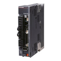
MR-J4-15KA4(-RJ)
Mitsubishi Electric MR-J4-15KA4(-RJ) Manuals
Manuals and User Guides for Mitsubishi Electric MR-J4-15KA4(-RJ). We have
1
Mitsubishi Electric MR-J4-15KA4(-RJ) manual available for free PDF download: Instruction Manual
Mitsubishi Electric MR-J4-15KA4(-RJ) Instruction Manual (908 pages)
General-Purpose AC Servo MELSERVO-J4 General-Purpose Interface MR-J4 series SERVO AMPLIFIER
Brand:
Mitsubishi Electric
| Category:
Servo Drives
| Size: 10.2 MB
Table of Contents
Table of Contents
10
Summary
20
Function Block Diagram
22
Servo Amplifier Standard Specifications
30
Combinations of Servo Amplifiers and Servo Motors
37
Function List
40
Connector
41
Model Designation
43
Structure
44
Removal and Reinstallation of the Front Cover
59
Configuration Including Peripheral Equipment
61
Installation Direction and Clearances
77
Keeping out of Foreign Materials
79
Inspection Items
80
Parts Having Service Life
81
Restrictions When Using this Product at Altitude Exceeding 1000 M and up to 2000 M above Sea Level
82
Input Power Supply Circuit
85
V Class
86
V Class
91
V Class
94
I/O Signal Connection Example
95
Speed Control Mode
98
Torque Control Mode
101
Explanation of Power Supply System
104
Power-On Sequence
105
Wiring CNP1, CNP2, and CNP3
106
Connectors and Pin Assignment
110
Signal (Device) Explanations
113
Detailed Explanation of Signals
123
Speed Control Mode
128
Torque Control Mode
130
Position/Speed Control Switching Mode
133
Speed/Torque Control Switching Mode
135
Torque/Position Control Switching Mode
137
Forced Stop Deceleration Function
138
Base Circuit Shut-Off Delay Time Function
140
Vertical Axis Freefall Prevention Function
141
Alarm Occurrence Timing Chart
142
When You Do Not Use the Forced Stop Deceleration Function
143
Interfaces
144
Detailed Explanation of Interfaces
146
Source I/O Interfaces
150
Servo Motor with an Electromagnetic Brake
152
Timing Chart
154
Grounding
158
Switching Power on for the First Time
161
Wiring Check
162
Surrounding Environment
165
Stop
166
Test Operation
167
Parameter Setting
168
Startup in Speed Control Mode
171
Stop
172
Test Operation
173
Parameter Setting
174
Startup in Torque Control Mode
176
Test Operation
177
Parameter Setting
178
Trouble at Start-Up
179
Display and Operation Sections
180
Display Flowchart
181
Status Display Mode
182
Diagnostic Mode
189
Alarm Mode
191
Parameter Mode
192
External I/O Signal Display
194
Output Signal (DO) Forced Output
197
Test Operation Mode
198
Parameter List
205
Gain/Filter Setting Parameters ([Pr. PB_ _ ])
206
Extension Setting Parameters ([Pr. PC_ _ ])
208
I/O Setting Parameters ([Pr. PD_ _ ])
210
Extension Setting 2 Parameters ([Pr. PE_ _ ])
211
Extension Setting 3 Parameters ([Pr. PF_ _ ])
213
Linear Servo Motor/DD Motor Setting Parameters ([Pr. PL_ _ ])
214
Option Setting Parameters ([Pr. Po_ _ ])
215
Detailed List of Parameters
216
Gain/Filter Setting Parameters ([Pr. PB_ _ ])
229
Extension Setting Parameters ([Pr. PC_ _ ])
243
I/O Setting Parameters ([Pr. PD_ _ ])
257
Extension Setting 2 Parameters ([Pr. PE_ _ ])
265
Extension Setting 3 Parameters ([Pr. PF_ _ ])
268
Linear Servo Motor/DD Motor Setting Parameters ([Pr. PL_ _ ])
271
Option Setting Parameters ([Pr. Po_ _ ])
274
Different Adjustment Methods
280
Adjustment Using MR Configurator2
281
One-Touch Tuning
282
One-Touch Tuning Flowchart
284
Display Transition and Operation Procedure of One-Touch Tuning
287
Caution for One-Touch Tuning
301
Auto Tuning
302
Auto Tuning Mode Basis
303
Adjustment Procedure by Auto Tuning
304
Response Level Setting in Auto Tuning Mode
305
Manual Mode
306
Gain Adjustment Mode
309
Filter Setting
312
Machine Resonance Suppression Filter
313
Adaptive Filter II
316
Shaft Resonance Suppression Filter
319
Low-Pass Filter
320
Command Notch Filter
325
Gain Switching Function
327
Function Block Diagram
328
Parameter
329
Gain Switching Procedure
332
Tough Drive Function
336
Instantaneous Power Failure Tough Drive Function
338
Compliance with SEMI-F47 Standard
342
Model Adaptive Control Disabled
345
Lost Motion Compensation Function
346
Super Trace Control
349
Explanation for the Lists
352
Alarm List
353
Warning List
362
Overload Protection Characteristics
388
Power Supply Capacity and Generated Loss
392
Dynamic Brake Characteristics
395
Dynamic Brake Operation
396
Permissible Load to Motor Inertia When the Dynamic Brake Is Used
399
Cable Bending Life
400
Inrush Currents at Power-On of Main Circuit and Control Circuit
401
Cable/Connector Sets
404
Combinations of Cable/Connector Sets
405
MR-D05UDL3M-B STO Cable
409
Battery Cable/Junction Battery Cable
410
Regenerative Options
411
Selection of Regenerative Option
413
Parameter Setting
416
Dimensions
421
FR-BU2-(H) Brake Unit
425
Selection
426
Connection Example
427
Dimensions
437
FR-RC-(H) Power Regeneration Converter
439
FR-CV-(H) Power Regeneration Common Converter
445
Selection Example
446
Junction Terminal Block MR-TB50
454
MR Configurator2
457
System Configuration
458
Precautions for Using USB Communication Function
459
Battery
460
MR-BAT6V1SET Battery
461
MR-BAT6V1BJ Battery for Junction Battery Cable
465
MR-BAT6V1SET-A Battery
469
MR-BT6VCASE Battery Case
473
MR-BAT6V1 Battery
479
Selection Example of Wires
480
Molded-Case Circuit Breakers, Fuses, Magnetic Contactors
484
Power Factor Improving DC Reactors
487
Power Factor Improving AC Reactors
491
Relays (Recommended)
494
Noise Reduction Techniques
495
Earth-Leakage Current Breaker
502
EMC Filter (Recommended)
505
External Dynamic Brake
512
Panel through Attachment (MR-J4ACN15K/MR-J3ACN)
519
Summary
524
Restrictions
525
Parameter Setting
526
Battery
527
Using MR-BAT6V1BJ Battery for Junction Battery Cable
528
Using MR-BT6VCASE Battery Case
529
Standard Connection Example
530
Signal Explanation
531
Startup Procedure
532
Absolute Position Data Transfer Protocol
533
Transfer Method
534
Home Position Setting
543
Use of Servo Motor with an Electromagnetic Brake
545
How to Process the Absolute Position Data at Detection of Stroke End
546
Communication-Based Absolute Position Transfer System
549
Introduction
554
Residual Risks of the STO Function
555
Specifications
556
Maintenance
557
Signal (Device) Explanations
558
Connection Example
559
External I/O Signal Connection Example Using an MR-J3-D05 Safety Logic Unit
560
External I/O Signal Connection Example Using an External Safety Relay Unit
563
Detailed Description of Interfaces
564
Source I/O Interface
565
Structure
569
Precautions for Using RS-422/RS-232C/USB Communication Function
571
Communication Specifications
572
Protocol
573
Character Codes
574
Error Codes
575
Retry Processing
576
Communication Procedure Example
577
Command and Data No. List
578
Writing Commands
584
Detailed Explanations of Commands
586
Status Display Mode
588
Parameter
589
External I/O Signal Status (DIO Diagnosis)
593
Input Device On/Off
596
Disabling/Enabling I/O Devices (DIO)
597
Input Devices On/Off (Test Operation)
598
Test Operation Mode
599
Output Signal Pin On/Off (Output Signal (DO) Forced Output)
603
Alarm History
604
Current Alarm
605
Other Commands
606
Functions and Configuration
608
Configuration Including Peripheral Equipment
609
Signals and Wiring
613
Operation and Functions
614
Magnetic Pole Detection
618
Home Position Return
625
Test Operation Mode in MR Configurator2
630
Function
631
Absolute Position Detection System
634
Characteristics
635
Power Supply Capacity and Generated Loss
636
Dynamic Brake Characteristics
637
Permissible Load to Motor Mass Ratio When the Dynamic Brake Is Used
638
Functions and Configuration
640
Configuration Including Peripheral Equipment
641
Signals and Wiring
642
Operation and Functions
643
Startup Procedure
644
Magnetic Pole Detection
645
Function
651
Absolute Position Detection System
653
Characteristics
654
Power Supply Capacity and Generated Loss
656
Dynamic Brake Characteristics
657
Functions and Configuration
661
Selecting Procedure of Control Mode
662
System Configuration
663
Load-Side Encoder
665
Configuration Diagram of Encoder Cable
666
MR-J4FCCBL03M Branch Cable
668
Operation and Functions
669
Home Position Return
676
Fully Closed Loop Control Error Detection Functions
679
Auto Tuning Function
680
Absolute Position Detection System under Fully Closed Loop System
681
About MR Configurator2
682
Functions and Configuration
684
Function Block Diagram
685
Servo Amplifier Standard Specifications
686
Combinations of Servo Amplifiers and Servo Motors
687
Function List
688
Model Definition
691
Parts Identification
692
Configuration Including Peripheral Equipment
693
Installation
694
Installation Direction and Clearances
695
Installation by DIN Rail
697
Signals and Wiring
699
Input Power Supply Circuit
700
Explanation of Power Supply System
702
Selection of Main Circuit Power Supply/Control Circuit Power Supply
705
I/O Signal Connection Example
706
Connectors and Pin Assignment
714
Signal (Device) Explanations
717
Alarm Occurrence Timing Chart
721
Interfaces (Internal Connection Diagram)
723
Grounding
725
Startup
726
Startup Procedure
727
Troubleshooting When "24 V ERROR" Lamp Turns on
728
Wiring Check
729
Surrounding Environment
730
Display Flowchart
731
Status Display Mode
732
One-Touch Tuning
737
Diagnostic Mode
741
Alarm Mode
744
Parameter Mode
746
External I/O Signal Display
751
Output Signal (DO) Forced Output
754
Test Operation Mode
755
Dimensions
757
Characteristics
758
Power Supply Capacity and Generated Loss
759
Inrush Currents at Power-On of Main Circuit and Control Circuit
761
Options and Peripheral Equipment
762
Combinations of Cable/Connector Sets
763
Selection Example of Wires
764
Communication Function (Mitsubishi Electric General-Purpose AC Servo Protocol)
765
Function Block Diagram
769
Structure
771
Installation and Removal of the MR-D01 Extension I/O Unit
772
Configuration Including Peripheral Equipment
776
Installation Direction and Clearances
778
Signals and Wiring
780
I/O Signal Connection Example
781
Connectors and Pin Assignment
796
Signal (Device) Explanations
798
Interface
804
Monitor Display with MR Configurator2
808
Dimensions
810
Options Peripheral Equipment
811
PS7DW-20V14B-F (Junction Terminal Block) (Recommended)
812
MR-TB50 (Junction Terminal Block)
814
Advertisement
Advertisement
Related Products
Mitsubishi Electric MR-J4-15KA(-RJ)
Mitsubishi Electric MR-J4-15KB(-RJ)
Mitsubishi Electric MR-J4-15KB4(-RJ)
Mitsubishi Electric MR-J4-15KGF
Mitsubishi Electric MR-J4-15KGF-RJ
Mitsubishi Electric MR-J4-15KB-RJ010
Mitsubishi Electric MR-J4-15KB4-RJ010
Mitsubishi Electric MELSERVO MR-J4-15KB
Mitsubishi Electric MR-J4-10B-RJ010
Mitsubishi Electric MR-J4-11KGF-RJ
Mitsubishi Electric Categories
Air Conditioner
Controller
Projector
Inverter
Heat Pump
More Mitsubishi Electric Manuals
Login
Sign In
OR
Sign in with Facebook
Sign in with Google
Upload manual
Upload from disk
Upload from URL