Sign In
Upload
Manuals
Brands
Mitsubishi Electric Manuals
Control Unit
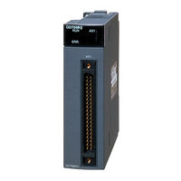
QD75MH4
Mitsubishi Electric QD75MH4 Manuals
Manuals and User Guides for Mitsubishi Electric QD75MH4. We have
1
Mitsubishi Electric QD75MH4 manual available for free PDF download: User Manual
Mitsubishi Electric QD75MH4 User Manual (834 pages)
Type QD75MH Positioning Module
Brand:
Mitsubishi Electric
| Category:
Control Unit
| Size: 8.43 MB
Table of Contents
Safety Instructions
2
Revisions
7
Table of Contents
8
About Manuals
15
Conformation to the EMC Directive
15
Using this Manual
15
Component List
16
Generic Terms and Abbreviations
16
Section 1 Product Specifications and Handling
18
Features of QD75MH
21
Positioning Control
21
Product Outline 1- 1 to
21
Purpose and Applications of Positioning Control
24
Mechanism of Positioning Control
26
Overview of Positioning Control Functions
27
Outline Design of Positioning System
37
Communicating Signals between QD75MH and each Module
38
Flow of All Processes
41
Flow of System Operation
41
Outline of Starting
43
Outline of Stopping
45
Outline for Restarting
47
General Image of System
49
Component List
51
Applicable System
53
How to Check the Function Version and SERIAL no
55
Performance Specifications
57
List of Functions
59
QD75MH Control Functions
59
QD75MH Main Functions
61
QD75MH Sub Functions and Common Functions
63
Combination of QD75MH Main Functions and Sub Functions
67
List of Input/Output Signals with PLC CPU
69
Specifications of Input/Output Signals with PLC CPU
69
Details of Input Signals (QD75MH PLC CPU)
70
Qd75Mh)
72
Electrical Specifications of Input Signals
73
Specifications of Interfaces with External Devices
73
Signal Layout for External Device Connection Connector
74
List of Input Signal Details
75
Interface Internal Circuit
76
External Circuit Design
77
Installation, Wiring and Maintenance Procedures
81
Outline of Installation, Wiring and Maintenance
81
Names of each Part
82
Handling Precautions
84
Installation
86
Precautions for Installation
88
Wiring
89
Precautions for Wiring
91
Confirming the Installation and Wiring
95
Items to Confirm When Installation and Wiring Are Completed
95
Disposal Instructions
96
Maintenance
96
Precautions for Maintenance
96
Parameters and Data Required for Control
99
Types of Data
99
Setting Items for Positioning Parameters
103
Setting Items for OPR Parameters
105
Setting Items for Servo Parameters
106
Setting Items for Positioning Data
108
Setting Items for Block Start Data
111
Setting Items for Condition Data
112
Types and Roles of Monitor Data
113
Types and Roles of Control Data
117
Basic Parameters 1
121
List of Parameters
121
Basic Parameters 2
125
Detailed Parameters 1
127
Detailed Parameters 2
135
OPR Basic Parameters
147
OPR Detailed Parameters
153
Servo Parameters (Basic Setting)
159
Servo Parameters (Gain • Filter Setting)
165
Servo Parameters (Expansion Setting)
177
Servo Parameters (Input/Output Setting)
183
List of Positioning Data
187
List of Block Start Data
203
List of Condition Data
209
List of Monitor Data
215
System Monitor Data
215
Axis Monitor Data
225
List of Control Data
245
System Control Data
245
Axis Control Data
247
Precautions for Creating Program
271
List of Devices Used
274
Creating a Program
284
General Configuration of Program
284
Positioning Control Operation Program
285
Positioning Program Examples
289
Initialization Program
321
Program Details
321
Start Details Setting Program
322
Start Program
324
Continuous Operation Interrupt Program
333
Restart Program
335
Stop Program
338
Configuration and Roles of QD75MH Memory
343
Buffer Memory Area Configuration
346
Data Transmission Process
349
Outline of OPR Control
365
Two Types of OPR Control
365
Machine OPR
368
Outline of the Machine OPR Operation
368
Machine OPR Method
369
OPR Method (1): Near-Point Dog Method
370
OPR Method (2): Count Method 1)
372
OPR Method (3): Count Method 2)
374
OPR Method (4): Data Set Method
376
Fast OPR
377
Outline of the Fast OPR Operation
377
Outline of Major Positioning Controls
381
Data Required for Major Positioning Control
383
Operation Patterns of Major Positioning Controls
384
Designating the Positioning Address
394
Confirming the Current Value
395
Control Unit "Degree" Handling
397
Interpolation Control
404
Relation between each Control and Positioning Data
404
Setting the Positioning Data
404
1-Axis Linear Control
406
2-Axis Linear Interpolation Control
408
3-Axis Linear Interpolation Control
412
4-Axis Linear Interpolation Control
418
1-Axis Fixed-Feed Control
423
2-Axis Fixed-Feed Control (Interpolation)
425
3-Axis Fixed-Feed Control (Interpolation)
427
4-Axis Fixed-Feed Control (Interpolation)
431
2-Axis Circular Interpolation Control with Sub Point Designation
433
2-Axis Circular Interpolation Control with Center Point Designation
439
1-Axis Speed Control
447
2-Axis Speed Control
450
3-Axis Speed Control
453
4-Axis Speed Control
457
Speed-Position Switching Control (INC Mode)
462
Speed-Position Switching Control (ABS Mode)
467
Speed-Position Switching Control (ABS Mode)
470
Position-Speed Switching Control
478
Current Value Changing
485
NOP Instruction
490
JUMP Instruction
491
Loop
493
Lend
494
Outline of High-Level Positioning Control
497
Data Required for High-Level Positioning Control
498
Block Start Data" and "Condition Data" Configuration
499
High-Level Positioning Control Execution Procedure
501
Relation between Various Controls and Block Start Data
502
Setting the Block Start Data
502
Block Start (Normal Start)
503
Condition Start
505
Wait Start
506
Simultaneous Start
507
Repeated Start (for Loop)
508
Repeated Start (for Condition)
509
Restrictions When Using the NEXT Start
510
Relation between Various Controls and the Condition Data
511
Setting the Condition Data
511
Condition Data Setting Examples
514
Multiple Axes Simultaneous Start Control
515
Start Program for High-Level Positioning Control
518
Starting High-Level Positioning Control
518
Example of a Start Program for High-Level Positioning Control
519
Outline of Manual Control
523
Three Manual Control Methods
523
JOG Operation
525
Outline of JOG Operation
525
JOG Operation Execution Procedure
528
Setting the Required Parameters for JOG Operation
529
Creating Start Programs for JOG Operation
531
JOG Operation Example
534
Inching Operation
538
Outline of Inching Operation
538
Inching Operation Execution Procedure
541
Setting the Required Parameters for Inching Operation
542
Creating a Program to Enable/Disable the Inching Operation
543
Inching Operation Example
546
Manual Pulse Generator Operation
548
Outline of Manual Pulse Generator Operation
548
Manual Pulse Generator Operation Execution Procedure
552
Setting the Required Parameters for Manual Pulse Generator Operation
553
Creating a Program to Enable/Disable the Manual Pulse Generator Operation
554
Outline of Sub Functions
559
OPR Retry Function
561
Sub Functions Specifically for Machine OPR
561
OP Shift Function
565
Backlash Compensation Function
568
Functions for Compensating the Control
568
Electronic Gear Function
570
Near Pass Function
577
Functions to Limit the Control
580
Speed Limit Function
580
Torque Limit Function
582
Software Stroke Limit Function
586
Hardware Stroke Limit Function
592
Forced Stop Function
596
Functions to Change the Control Details
599
Speed Change Function
599
Override Function
606
Acceleration/Deceleration Time Change Function
609
Torque Change Function
613
Absolute Position System
616
Other Functions
618
Step Function
618
Skip Function
623
M Code Output Function
626
Teaching Function
630
Target Position Change Function
636
Command In-Position Function
640
Acceleration/Deceleration Processing Function
643
Pre-Reading Start Function
646
Deceleration Start Flag Function
651
Stop Command Processing for Deceleration Stop Function
655
Speed Control 10 X Multiplier Setting for Degree Axis Function
658
Operation Setting for Incompletion of OPR Function
660
Servo ON/OFF
662
Follow up Function
663
Outline of Common Functions
665
Parameter Initialization Function
666
Execution Data Backup Function
668
External Signal Selection Function
670
External I/O Signal Logic Switching Function
671
Interlock During Dedicated Instruction Is Executed
673
List of Dedicated Instructions
673
Pstrt1, Pstrt2, Pstrt3, Pstrt4
674
Teach1, Teach2, Teach3, Teach4
678
Pfwrt
682
Pinit
686
Error and Warning Details
691
List of Errors
695
QD75MH Detection Error
695
MR-J3-B Detection Error
725
List of Warnings
739
QD75MH Detection Warning
739
MR-J3-B Detection Warning
745
LED Display Functions
749
Appendix 1 Functions
752
Appendix 1.1 Multiple CPU Correspond Function
752
Appendix 1.2 the Combination of Software Package for QD75MH and QCPU
752
Appendix 2 Positioning Data (No.1 to 600) List of Buffer Memory Addresses
753
Appendix 3 Connection with Servo Amplifiers
777
Appendix 3.1 Connection of SSCNET Cables
777
Appendix 3.2 Wiring of SSCNET Cables
779
Appendix 4 Connection with External Device Connector
783
Appendix 4.1 Connector
783
Appendix4.2 Wiring of Manual Pulse Generator Cable
785
Appendix 5 Comparisons with Conventional Positioning Modules
786
Appendix 5.1 Comparisons with QD75P Model
786
Appendix 5.2 Comparisons with QD75M1/ QD75M2/ QD75M4 Models
787
Appendix 6 Positioning Control Troubleshooting
800
Appendix 7 List of Buffer Memory Addresses
806
Appendix 8 External Dimension Drawing
820
Index
822
Advertisement
Advertisement
Related Products
Mitsubishi Electric QD75MH1
Mitsubishi Electric QD75MH2
Mitsubishi Electric QD75P1N
Mitsubishi Electric QD75P2N
Mitsubishi Electric QD75D4N
Mitsubishi Electric QD75P2
Mitsubishi Electric QD75P4
Mitsubishi Electric QD75D2
Mitsubishi Electric QD75P4N
Mitsubishi Electric QD75D2N
Mitsubishi Electric Categories
Air Conditioner
Controller
Projector
Inverter
Heat Pump
More Mitsubishi Electric Manuals
Login
Sign In
OR
Sign in with Facebook
Sign in with Google
Upload manual
Upload from disk
Upload from URL