Sign In
Upload
Manuals
Brands
Siemens Manuals
Protection Device
7SV512
Siemens 7SV512 Manuals
Manuals and User Guides for Siemens 7SV512. We have
1
Siemens 7SV512 manual available for free PDF download: Instruction Manual
Siemens 7SV512 Instruction Manual (136 pages)
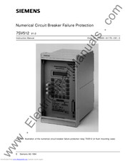
Numerical Circuit Breaker Failure Protection V1.0
Brand:
Siemens
| Category:
Protection Device
| Size: 1.58 MB
Table of Contents
Table of Contents
5
Introduction
9
Application
9
Features
10
Design
11
Arrangements
11
Dimensions
13
Ordering Data
15
Technical Data
16
General Data
16
Inputs/Outputs
16
Electrical Tests
18
Mechanical Stress Tests
19
Climatic Stress Tests
20
Service Conditions
20
Design
20
Circuit Breaker Failure Protection
21
Circuit Breaker Pole Discrepancy Supervision
21
Ancillary Functions
22
Method of Operation
23
Operation of Complete Unit
23
Circuit Breaker Failure Protection
25
General
25
Current Flow Monitoring
26
Processing of the Circuit Breaker Auxiliary Contacts
27
Initiation Conditions and Delay Times
29
Common Phase Initiation
29
Two-Stage Breaker Failure Protection with Common Phase Initiation
30
Phase Segregated Initiation
30
Combined Initiation Conditions
33
Function Examples
33
Circuit Breaker Not Fully Operational
34
Transfer Trip to the Remote End Circuit Breaker
34
Hardware Supervision and Blocking
34
End Fault Protection
36
Circuit Breaker Pole Discrepancy Supervision
36
Ancillary Functions
37
Processing of Annunciations
37
Indicators and Binary Outputs (Signal Relays)
37
Information on the Display Panel or to a Personal Computer
37
Information to a Central Unit (Optional)
38
Data Storage and Transmission for Fault Recording
38
Operating Measurements and Conversion
38
Monitoring Functions
39
Hardware Monitoring
39
Software Monitoring
40
Monitoring of External Measuring Transformer Circuits
40
Installation Instructions
41
Unpacking and Repacking
41
Preparations
41
Mounting and Connections
42
Model 7SV512K
42
Checking the Rated Data
42
Control D.C. Voltage of Binary Inputs
42
Checking the LSA Data Transmission Link
44
Connections
45
Checking the Connections
47
Configuration of Operational Functions
48
Operational Preconditions
48
Settings for Operating Parameters
48
Configuration of the Device Functions
51
Introduction
51
Programming the Scope of Functions
52
Marshalling of Binary Inputs, Binary Outputs and LED Indicators
53
Introduction
53
Marshalling of the Binary Inputs
55
Marshalling of the Signal Output Relays
58
Marshalling of the LED Indicators
61
Marshalling of the Command (Trip) Relays
63
Configuration Parameters for Localized Substation Automation
65
Operating Instructions
67
Safety Precautions
67
Dialog with the Relay
67
Membrane Keyboard and Display Panel
67
Operation with a Personal Computer
68
Operational Preconditions
68
Representation of the Relay (Front View)
69
Setting the Functional Parameters
70
6.3.1. Introduction
70
Parameterizing Procedure
70
Selectable Parameter Sets
71
Setting of Date and Time
72
Initial Displays
73
Power System Data
73
Settings for Circuit Breaker Failure Protection
75
Settings for Fault Recording
80
Settings for Measured Value Monitoring
81
Settings for Breaker Pole Discrepancy Supervision
82
Annunciations
83
Introduction
83
Operational Annunciations
84
Fault Annunciations
88
Circuit Breaker Operation Statistics
91
Read-Out of Operational Measured Values
92
Operational Control Facilities
93
Adjusting and Synchronizing the Real Time Clock
93
Off/On Control of Part Functions of the Device
95
Selection of Parameter Sets
97
Read-Out of Settings of a Parameter Set
97
Change-Over of the Active Parameter Set from the Operating Panel
97
Change-Over of the Active Parameter Set Via Binary Inputs
98
Testing and Commissioning
99
General
99
Testing the Circuit Breaker Failure Protection
100
Testing the End Fault Protection
101
Testing the Circuit Breaker Pole Discrepancy Supervision
101
Commissioning Using Primary Tests
102
Checking the Initiation Conditions
102
Checking the Local Trip with Breaker Failure Criterion from the Auxiliary Contacts
103
Checking the Local Trip and the Current Circuits
103
Checking the Intertrip to the Opposite Feeder End
104
Checking the Bus-Bar Trip
104
Putting the Relay into Operation
105
Maintenance and Fault Tracing
106
Routine Checks
106
Replacing the Clock Module
107
Fault Tracing
108
Replacing the Mini-Fuse
109
Repairs
111
Storage
111
Appendix
112
General Diagrams
113
Connection Diagrams
116
C Tables
119
Advertisement
Advertisement
Related Products
Siemens SIPROTEC 7SS52
Siemens SIPROTEC 7SD80
Siemens Siprotec 7SD600
Siemens 7SA513 Series
Siemens 7SJ82
Siemens 7SJ85
Siemens SIPROTEC 7SJ80
Siemens SIPROTEC 7SJ64
Siemens SIPROTEC 7ST61
Siemens 7SG23 MSCDN - MP2A
Siemens Categories
Industrial Equipment
Controller
Control Unit
Oven
Washer
More Siemens Manuals
Login
Sign In
OR
Sign in with Facebook
Sign in with Google
Upload manual
Upload from disk
Upload from URL