Sign In
Upload
Manuals
Brands
Siemens Manuals
Controller
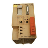
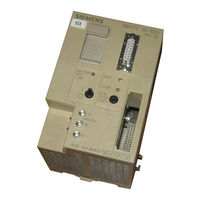
SIMATIC S5-100U
Siemens SIMATIC S5-100U Manuals
Manuals and User Guides for Siemens SIMATIC S5-100U. We have
2
Siemens SIMATIC S5-100U manuals available for free PDF download: System Manual, User Manual
Siemens SIMATIC S5-100U User Manual (512 pages)
SIMATIC S5 Programmable Controller
Brand:
Siemens
| Category:
Controller
| Size: 6.39 MB
Table of Contents
Table of Contents
4
The SIMATIC S5 System Family
16
Table of Contents
20
2 Technical Description
22
Programmable Controller Design
22
Principle of Operation for the Programmable Controller
24
Functional Units
24
Functional Units of the S5-100U
24
Example of an Arithmetic Logic Unit's Mode of Operation
26
Accumulator Design
26
Retentive and Non-Retentive Operands
26
Mode of Operation for the External I/O Bus
27
The S5-100U
27
Structure of the External I/O Bus
27
Data Cycle
28
Number of Bits Per Module in the Shift Register
29
Installation Guidelines/Installing S5-100U Components
31
3 Installation Guidelines
31
Installing S5-100U Components
31
Wiring
31
Connection Methods: Screw-Type Terminals and Crimp Snap-In
31
Connecting the Power Supply to the S5-100U
31
Electrical Configuration
31
Electrical Configuration for the S5-100U
31
Electrical Configuration with External I/Os
31
Wiring Arrangement, Shielding, and Measures to
31
Guard against Electromagnetic Interference
31
Installing S5-100U Components
33
Assembling a Tier
33
Installation Guidelines
33
3.1.2 Multi-Tier Expansion
37
Cabinet Mounting
39
Vertical Mounting
40
Connection Methods: Screw-Type Terminals and Crimp Snap-In
41
Connecting Digital Modules
45
Connecting the Digital Input/Output Module
50
Non-Floating and Floating Configurations
57
Wiring Arrangement
61
Shielding of Devices and Cables
63
Measures to Guard against Electromagnetic Interference
64
Protective Devices and Insulation Monitoring Devices
68
Start-Up and Program Tests
70
4 Start-Up and Program Tests
72
Operating Instructions
72
CPU Operator Panel
72
4.1.2 Operating Modes
72
4.1.3 Performing an Overall Reset on the Programmable Controller
73
Starting up a System
74
Suggestions for Configuring and Installing the Product
74
Procedures for Starting up the Programmable Controller
75
Loading the Program into the Programmable Controller
76
Backing up the Program
78
Backing up the Program on a Memory Submodule
78
Function of the Back-Up Battery
79
Program-Dependent Signal Status Display "STATUS
79
Direct Signal Status Display "STATUS VAR
80
Forcing Outputs, "FORCE", for CPU 103 and Higher
81
Forcing Variables, "FORCE VAR
81
Search Function
82
Program Check, for CPU 103 and Higher
82
Table of Contents
84
5 Diagnostics and Troubleshooting
86
Indication of Errors by Leds
86
CPU Malfunctions
86
ISTACK" Analysis Function
86
Interrupt Analysis
90
Errors During Program Copying
91
Explanation of the Mnemonics Used in "ISTACK
92
Program Errors
94
Locating the Error Address
94
Tracing the Program with the "BSTACK" Function
97
5.4 I/O Faults
99
5.5 System Parameters
99
The Last Resort
100
Addressing
101
6 Addressing
103
Slot Numbering
103
Digital Modules
106
Analog Modules
107
Combined Input Modules and Output Modules
108
Output Modules with Error Diagnostics
108
Digital Input/Output Module, 16 Inputs, 16 Outputs, 24 V DC
109
For All Cpus Version 8MA02 and Higher and for CPU 102, Version 8MA01, Revision 5 and Higher
109
Function Modules
109
The Structure of Process Image Input and Output Tables
110
Accessing the Process Image Input Table (PII)
112
Accessing the Process Image Output Table (PIQ)
113
Accessing the Interrupt PII
114
Interrupt Process Images and Time-Controlled Program Processing in OB13 for CPU 103, Version 8MA02 and Higher
114
Accessing the Interrupt PIQ
116
RAM Address Assignments
117
Introduction to Step
119
Methods of Representation
121
STEP 5 Operations
121
Writing a Program
121
Methods of Representation
122
Circuit Diagram Conversion
123
Operand Areas
123
Linear Programming
124
Program Structure
124
Structured Programming
125
Block Types
127
Organization Blocks
129
Organization Blocks
130
Function Blocks
131
Program Blocks
131
Sequence Blocks, for CPU 103 and Higher
131
Data Blocks
136
Program Processing
138
START-UP Program Processing
144
Cyclic Program Processing
146
Time-Controlled Program Processing, for CPU 103 Version 8MA02 and Higher
148
Version 8MA02 and Higher
149
Processing Blocks
150
Number Representation
151
Table of Contents
154
Basic Operations
156
STEP 5 Operations
156
Boolean Logic Operations
157
Set/Reset Operations
162
Load and Transfer Operations
165
Timer Operations
170
Counter Operations
180
8.1.6 Comparison Operations
185
Arithmetic Operations
186
Block Call Operations
188
Other Operations
193
Supplementary Operations
194
Load Operation, for CPU 103 and Higher
195
Enable Operation, for CPU 103 and Higher
196
Bit Test Operations, for CPU 103 and Higher
197
Digital Logic Operations
199
Shift Operations
203
Conversion Operations
205
Decrement/Increment, for CPU 103 and Higher
207
Disable/Enable Interrupt, for CPU 103 Version 8MA02 and Higher
208
DO" Operation, for CPU 103 and Higher
209
8.2.10 Jump Operations
211
8.2.11 Substitution Operations, for CPU 103 and Higher
213
Load and Transfer Operations
219
Set Operations
219
System Operations, for CPU 103 and Higher
219
Arithmetic Operations
222
Other Operations
223
Condition Code Generation
224
Momentary-Contact Relay/Edge Evaluation
226
Sample Programs
226
Clock/Clock-Pulse Generator
228
9 Integrated Blocks and Their Functions
229
Integrated Blocks and Their Functions
231
Setting the Address for the Parameter Error Code in DB1
232
Assigning Parameters in DB1
234
How to Recognize and Correct Parameter Errors
236
Transferring DB1 Parameters to the Programmable Controller
239
Reference Guide for Setting Parameters in DB1
240
Defining System Characteristics in DB1
241
Code Converter : B4 - FB240 -
242
Multiplier : 16 - FB242 -
243
Analog Value Conditioning Modules FB250 and FB251
244
OB251 PID Algorithm for CPU 103 Version 8MA02 and Higher
245
10 Interrupt Processing, for CPU 103 Version 8MA02 and Higher
257
Calculating Interrupt Reaction Times
263
Analog Value Processing
264
11 Analog Value Processing
267
Two-Wire Connection of Voltage Sensors
269
Two-Wire Connection of Current Sensors
270
Connection of Resistance Thermometers
272
Start-Up of Analog Input Modules
273
Analog Value Representation of Analog Input Modules
277
Analog Output Modules
285
Analog Value Representation of Analog Output Modules
286
Analog Value Conversion: Function Blocks FB250 and FB251
288
12 The Integral Real-Time Clock, for CPU 103 Version 8MA02 and Higher
293
The Integral Real-Time Clock, for CPU 103 Version 8MA02 and Higher
295
And Higher
296
Reading the Current Clock Time and the Current Date
297
DB1 Parameters Used for the Integral Real-Time Clock
298
Programming the Integral Real-Time Clock in DB1 for CPU 103 Version 8MA03 and Higher
299
Setting the Prompt Time in DB1
300
Setting the Operating Hours Counter in DB1
301
Structure of the Clock Data Area
302
Structure of the Status Word and How to Scan It
306
In the System Data Area
309
User Program
315
Programming the Prompt Function
319
Programming the Operating Hours Counter
324
Entering the Clock Time Correction Factor
329
13 Connecting the S5-100U to SINEC L1, for CPU 102 and Higher
330
Connecting the S5-100U to SINEC L1, for CPU 102 and Higher
332
How to Program in a Function Block, for CPU 102 and Higher
333
Setting Parameters in DB1, for CPU 103 and Higher
336
Coordinating Data Exchange in the Control Program
338
Sending Data
339
Receiving Data
340
Programming the Messages in a Function Block
342
14 Module Spectrum
344
Module Spectrum
345
Power Supply Modules
346
Central Processing Units
348
Bus Units
351
Interface Modules
355
Digital Modules
357
Digital Output Modules
366
Digital Input/Output Modules
376
Analog Modules
378
Analog Output Modules
396
Function Modules
400
15 Function Modules
402
Timer Module 2×0.3 to 300 S
405
Simulator Module
408
Diagnostic Module
410
Counter Module 2×0 to 500 Hz
413
Counter Module 25/500 Khz
418
Installation Guidelines
421
Data Transfer
426
Functional Description of the Counter Mode
428
Functional Description of the Position Decoder
430
Entering New Setpoints for the Counter and Position Decoder
439
Addressing
440
Closed-Loop Control Module IP 262
442
Positioning Module IP 266
446
Stepper Motor Control Module IP 267
450
Communications Modules
453
Communications Module CP 521 BASIC
456
A.1 Operations List
459
A.1.2 Supplementary Operations
466
A.1.3 System Operations, for CPU 102 and Higher
471
A.1.4 Evaluation of CC 1 and CC 0
472
A.2 Machine Code Listing
473
A.3 List of Abbreviations
476
B Dimension Drawings
479
C Active and Passive Faults in Automation Equipment
489
D Information for Ordering Accessories
491
E Reference Materials
498
F Siemens Addresses Worldwide
500
Advertisement
Siemens SIMATIC S5-100U System Manual (553 pages)
SIMATIC S5 series CPU 100/102/103
Brand:
Siemens
| Category:
Controller
| Size: 5.91 MB
Table of Contents
Technical Description
20
The SIMATIC S5 System Family
21
Technical Description
25
Principle of Operation for the Programmable Controller
29
Mode of Operation for the External I/O Bus
32
Installation Guidelines
37
Installation Guidelines
39
Cabinet Mounting
45
Vertical Mounting
46
Wiring
47
Connecting Digital Modules
51
Connecting the Digital Input/Output Module
56
Electrical Configuration
58
Electrical Configuration with External I/Os
59
Non-Floating and Floating Configurations
63
Running Cables Inside and Outside a Cabinet
67
Running Cables Outside Buildings
68
Equipotential Bonding
69
Shielding Cables
70
Special Measures for Interference-Free Operation
71
Start-Up and Program Tests
73
Start-Up and Program Tests
75
Performing an Overall Reset on the Programmable Controller
76
Starting up a System
77
Procedures for Starting up the Programmable Controller
78
Loading the Program into the Programmable Controller
79
Backing up the Program
81
Function of the Back-Up Battery
82
Direct Signal Status Display "STATUS VAR"
83
Forcing Outputs, "FORCE", for CPU 103 and Higher
84
Search Function
85
Diagnostics and Troubleshooting
87
Diagnostics and Troubleshooting
89
Interrupt Analysis
92
Errors During Program Copying
93
Explanation of the Mnemonics Used in "ISTACK"
94
Program Errors
96
Tracing the Program with the "BSTACK" Function
99
I/O Faults
100
The Last Resort
101
Addressing
103
Addressing
105
Digital Modules
108
Analog Modules
109
Combined Input Modules and Output Modules
110
For All Cpus Version 8MA02 and Higher and for CPU 102, Version 8MA01, Revision 5 and Higher
111
The Structure of Process Image Input and Output Tables
112
Accessing the Process Image Input Table (PII)
114
Accessing the Process Image Output Table (PIQ)
115
Accessing the Interrupt PII
116
Accessing the Interrupt PIQ
118
RAM Address Assignments
119
Introduction to STEP 5
121
STEP 5 Operations
123
Operand Areas
125
Program Structure
126
Structured Programming
127
Block Types
129
Organization Blocks
131
Program Blocks
133
Data Blocks
138
Program Processing
140
Program Processing with CPU 102
141
START-UP Program Processing
146
Cyclic Program Processing
148
Time-Controlled Program Processing, for CPU 103 Version 8MA02 and Higher
150
Version 8MA02 and Higher
151
Processing Blocks
152
Number Representation
153
STEP 5 Operations
159
Boolean Logic Operations
160
Set/Reset Operations
165
Load and Transfer Operations
168
Timer Operations
173
Counter Operations
183
Comparison Operations
188
Arithmetic Operations
189
Block Call Operations
191
Other Operations
196
Supplementary Operations
197
Load Operation, for CPU 103 and Higher
198
Enable Operation, for CPU 103 and Higher
199
Bit Test Operations, for CPU 103 and Higher
200
Digital Logic Operations
202
Shift Operations
206
Conversion Operations
208
Decrement/Increment, for CPU 103 and Higher
210
Disable/Enable Interrupt, for CPU 103 Version 8MA02 and Higher
211
DO" Operation, for CPU 103 and Higher
212
Jump Operations
214
Substitution Operations, for CPU 103 and Higher
216
System Operations, for CPU 103 and Higher
222
Arithmetic Operations
225
Other Operations
226
Condition Code Generation
227
Sample Programs
229
Clock/Clock-Pulse Generator
231
Integrated Blocks and Their Functions
233
Integrated Blocks and Their Functions
235
Setting the Address for the Parameter Error Code in DB1
236
Assigning Parameters in DB1
238
How to Recognize and Correct Parameter Errors
240
Transferring DB1 Parameters to the Programmable Controller
243
Reference Guide for Setting Parameters in DB1
244
Defining System Characteristics in DB1
245
Code Converter : B4 - FB240 -
246
Multiplier : 16 - FB242 -
247
Analog Value Conditioning Modules FB250 and FB251
248
OB251 PID Algorithm for CPU 103 Version 8MA02 and Higher
249
Interrupt Processing
261
Calculating Interrupt Reaction Times
267
Analog Value Processing
269
Analog Value Processing
273
Two-Wire Connection of Voltage Sensors
275
Two-Wire Connection of Current Sensors
276
Connection of Resistance Thermometers
278
Start-Up of Analog Input Modules
279
Analog Value Representation of Analog Input Modules
283
Analog Output Modules
291
Analog Value Representation of Analog Output Modules
292
Analog Value Conversion: Function Blocks FB250 and FB251
294
The Integral Real-Time Clock, for CPU 103 Version 8MA02 and Higher
301
And Higher
302
Reading the Current Clock Time and the Current Date
303
DB1 Parameters Used for the Integral Real-Time Clock
304
Programming the Integral Real-Time Clock in DB1 for CPU 103 Version 8MA03 and Higher
305
Setting the Prompt Time in DB1
306
Setting the Operating Hours Counter in DB1
307
Structure of the Clock Data Area
308
Structure of the Status Word and How to Scan It
312
Setting Parameters for the Clock Data Area and the Status Word in the System Data Area
315
User Program
321
Programming the Prompt Function
325
Programming the Operating Hours Counter
330
Entering the Clock Time Correction Factor
335
Connecting the S5-100U to SINEC L1, for CPU 102 and Higher
339
How to Program in a Function Block, for CPU 102 and Higher
340
Setting Parameters in DB1, for CPU 103 and Higher
343
Coordinating Data Exchange in the Control Program
345
Sending Data
346
Receiving Data
347
Programming the Messages in a Function Block
349
Module Spectrum
351
Module Spectrum
353
General Technical Specifications
355
Power Supply Modules
356
Central Processing Units
359
Bus Units
362
Interface Modules
366
Digital Modules
368
Digital Output Modules
378
Digital Input/Output Modules
388
Analog Modules
390
Analog Output Modules
408
Function Modules
413
Function Modules
415
Timer Module 2×0.3 to 300 S
418
Simulator Module
421
Diagnostic Module
423
Counter Module 2×0 to 500 Hz
426
Counter Module 25/500 Khz
431
Installation Guidelines
434
Data Transfer
439
Functional Description of the Counter Mode
441
Functional Description of the Position Decoder
443
Entering New Setpoints for the Counter and Position Decoder
452
Addressing
453
Closed-Loop Control Module IP 262
455
IP 263 Positioning Module
459
IP 264 Electronic Cam Controller Module
463
IP 265 High Speed Sub Control
466
Positioning Module IP 266
469
Stepper Motor Control Module IP 267
473
Communications Modules
476
Communications Module CP 521 BASIC
479
A Operations List, Machine Code and List of Abbreviations
481
A.1 Operations List
485
A.1.2 Supplementary Operations
492
A.1.3 System Operations, for CPU 102 and Higher
497
A.1.4 Evaluation of CC 1 and CC 0
498
A.2 Machine Code Listing
499
A.3 List of Abbreviations
502
Advertisement
Related Products
Siemens SIMATIC S5-115F
Siemens SIMATIC S5-115U
Siemens Simatic S5-101U
Siemens SIMATIC S5 3964(R)
Siemens SIMATIC S5 CPU Direct Driver
Siemens S55499-D385
Siemens S55499-D401
Siemens S55452-D312-A100
Siemens S55499-D298
Siemens SIMATIC NET S7-1200
Siemens Categories
Industrial Equipment
Controller
Control Unit
Oven
Washer
More Siemens Manuals
Login
Sign In
OR
Sign in with Facebook
Sign in with Google
Upload manual
Upload from disk
Upload from URL