Sign In
Upload
Manuals
Brands
Siemens Manuals
Controller
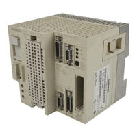
SIMATIC S5-115F
Siemens SIMATIC S5-115F Manuals
Manuals and User Guides for Siemens SIMATIC S5-115F. We have
2
Siemens SIMATIC S5-115F manuals available for free PDF download: User Manual, Manual
Siemens SIMATIC S5-115F User Manual (421 pages)
SIMATIC S5 Programmable Controller
Brand:
Siemens
| Category:
Controller
| Size: 4.77 MB
Table of Contents
Table of Contents
4
Preface
11
Introduction
12
System Overview
12
1 System Overview
17
Areas of Application
17
Regulations for Applications Requiring Official Approval
17
System Components
18
Power Supply
18
Central Processing Unit
19
Input and Output Modules
19
Intelligent Input/Output Modules and Communications Processors
20
Expansion Capability
20
Centralized Configuration
20
Distributed Configuration
20
Communications Systems
21
Operator-Process Communication, Process Visualization, and Programming
22
Software
22
Redundancy Structure
23
Hardware
23
Operating System - Additional Tasks
24
Control Programs
24
Programmer Functions
24
2 Technical Description
27
Modular Design
27
Principle of Operation of the Programmable Controller
29
Functional Units
29
Schematic Representation of the S5-115F
29
Program Scanning
31
Schematic Representation of Cyclic Program Scanning
31
Definition of the Short Discrepancy Time
33
Definition of the Long Discrepancy Time
34
Central Processing Unit Description
35
Execution Times of the CPU 942F in Μs (Rounded Off)
35
CPU Description
36
Schematic Representation of CPU 942F
37
Accessories
38
Backup Battery
38
Memory Submodules
38
Memory Submodules for Safety Mode
38
Programmers (PG)
39
Printers (PT)
39
Installation Guidelines
40
3 Installation Guidelines
43
Mounting Rack
43
Central Controller (CC)
43
Expansion Units (EU)
46
Mechanical Installation
54
Installing the Modules
54
Dimension Drawings
57
Cabinet Installation
60
Interconnecting the Two Subunits
61
Centralized Configurations
63
Distributed Configurations
64
Wiring
69
Connecting the PS 951F Power Supply Module
69
Connecting Digital Modules
70
Connecting Analog Modules
70
Front Connectors
71
Simulator
73
General Configuration
73
Power Supply
73
Electrical Installation with Field Devices
76
Connecting Nonfloating and Floating Modules
81
Installing Programmable Controllers in Conformity with EMC
83
Wiring Arrangement
84
Running Cables Outside Buildings
85
Equipotential Bonding
86
Shielding Cables
87
Special Measures for Interference-Free Operation
88
Checklist for the Installation of Programmable Controllers in Conformity with EMC
91
4 System Startup
94
Operating Instructions
94
Controls on the Power Supply Module and Central Processing Unit
94
Operating Modes
97
CPU Operation in "RUN" and "STOP" Modes
99
Cold Restart and Warm Restart
101
Battery Backup
106
Overall Reset
106
Steps for System Startup
107
Working with Input/Output Modules
111
System Startup Procedure
111
Safety Measures
111
Checking a Plant or Controlled System before Startup
112
5 Addressing
115
Address Structure
115
Digital Module Addresses
115
Analog Module Addresses
115
Slot Addressing
116
Handling Process Signals
119
Accessing the PII
120
Accessing the PIQ
121
Direct Access
122
CPU Address Assignment
124
Process Interrupt Generation with the 6ES5 434-7LA12 Digital Input Module
126
Functional Description
126
Initialization
126
Access
127
Programming Example
129
Analog Value Processing
130
6 Analog Value Processing
132
Analog Input Modules
132
460-7LA12 Analog Input Module
133
Connecting Sensors to the 460 Analog Input Module
133
Startup of the 460 Analog Input Module
139
Connecting Sensors to the 463 Analog Input Module
142
463-4U
142
Analog Input Module
145
Representation of the Digital Input Value
147
Digital Representation of a Measured Value (460 Analog Input Module)
147
Digital Representation of a Measured Value (463 Analog Input Module)
153
Wire-Break Signalling and Scanning
157
Analog Output Modules
159
Method of Operation of the Analog Output Modules
159
Digital Representation of an Analog Value
162
I/O Module Types
164
Analog Value Matching Blocks FB 250 and FB 251
168
Communications Capabilities
174
7 Communications Capabilities
177
Overview of Communications Capabilities
177
SINEC L1 Local Area Network
177
Master Controller
179
Safety-Related Connection of Several S5-115Fs
189
Connecting Several S5-115Fs with S5 Plcs of the U Range
198
Safety-Related and Fault-Tolerant Networking
206
The Mailbox Transfer Block FB 253
208
Programmers for the S5-115F
208
Programmer Connected to the Serial Interface of the CPU
208
Programmer Connected to SINEC L1 Master
209
CP 523 Serial I/O Module
210
Settings on the CP 523 Module
211
Use of the CP 523 in Print Mode
213
Use of the CP 523 in Communications Mode
220
Failsafe Characteristics of the CP 523
223
FB 252 Integral Function Block
224
8 Technical Specifications
228
General Technical Specifications
228
Description of the Modules
230
Mounting Racks (Crs, Ers)
230
Power Supply Module
233
Central Processing Unit
236
Digital Input Modules
237
Digital Output Modules
241
Digital Input/Output Modules
247
Analog Input Modules
253
Analog Output Modules
258
Communications Modules
264
Interface Modules
265
Accessories
269
Reliability, Availability and Safety of Electronic Control Systems
272
9 Reliability, Availability and Safety of Electronic Control Systems
274
Reliability of Electronic Control Systems
274
Failure Characteristics of Electronic Devices
275
Reliability of SIMATIC S5 Programmable Controllers and Components
275
Failure Distribution
276
Availability of Electronic Control Systems
276
Overview
276
Availability of the S5-115F Programmable Controller
277
Safety of Electronic Control Systems
278
Safe Inputs
278
Safe Binary Outputs
279
10 Rules Governing the Use of the S5-115F
280
The User Memory
284
The Logical Program Counter
284
Rules Governing the Use of the S5-115F
284
Response Times
285
Response Time in the Case of Cyclical Reading in and Output Via
286
Response Time in the Case of Direct Access in the Cyclic Program
286
The Process I/O Image
286
Response Time in the Case of Direct Access in the Time Interrupt ob (ob 13)
287
Response Time in the Case of Direct Access in the Process Interrupt ob (ob 2)
287
Response Times with the SINEC L1 LAN
288
Defining the PLC Cycle Time
290
Monitoring Times for Synchronization FB Calls (FB 254 SYNC)
292
Discrepancy Times
293
Limitations of STEP 5 Programming
294
Access to I/O Modules
294
Illegal Memory Area
295
Illegal STEP 5 Operations and Statements
295
Data Blocks Used
296
Jump Operations to Unloaded Blocks
296
Loadable Function Blocks
297
I/O Module Types
298
Digital Inputs
300
Implementation of Sensors
300
Requirements to be Met by the Sensor Signals
300
Type 1 Digital Input Modules
301
Type 2 Digital Input Modules
302
Type 3 Digital Input Modules
304
Checking Digital Input Modules in the Case of Non-Intermittent
307
Input Signals
307
Direct Read Access to DI Modules
307
Digital Input Module with Interrupt Capability (Interrupt DI)
308
Digital Output Modules (Dqs)
310
Type 8 Digital Output Modules (Dqs)
311
Type 9 and Type 10 Digital Output Modules
312
Connecting Actuators to Digital Output Modules (Dqs) (Types 9 and 10)
312
Checking Digital Output Modules Using Readback Digital Input Modules
320
Analog Input Modules
320
Type 13 Analog Input Modules
322
Type 14 Analog Input Modules
323
Type 15 Analog Input Modules
326
Checking Analog Input Modules Using Check Analog Output Modules
329
Type 16 Analog Input Modules
329
Analog Output Modules
333
Type 18 Analog Output Modules
333
I/O Type Assignment of Unused Digital Words
334
I/O Type Assignment of Unused Analog Channels
334
I/O Type Mixes
335
Relationship between Byte and Word Addressing
335
Address Grid
336
Responding to I/O Module Errors
340
Passivation of I/O Modules
342
Revoking Passivation of I/O Modules
343
Repair Procedure
349
Handling the Programmer
349
Connecting the Programmer
349
Operator Entry in the Programmer in Safety Mode
350
Sinec L1 Lan
351
Polling List
352
SINEC L1 Safety Time
352
Two-Channel SINEC L1 LAN
353
Individual Acceptance Test of the Safety-Related System
353
Planning Phase
353
Pre-Inspection
355
System Test
356
Appendices
358
A Evaluation of Error Dbs DB2 and DB3 Without COM 115F
359
B Slot Assignments
374
Power Supply Connector Pin Assignment
374
Connector Pin Assignments of the CPU
374
Connector Pin Assignments of Analog Input/Output Modules
374
Connector Pin Assignments of the Interface Modules
374
Connector Pin Assignments of the Symmetrical and Serial EU Interface Modules
374
Connector Pin Assignments of the Symmetrical and Serial CC Interface Modules
374
Connector Pin Assigments of the Asymmetrical IM 305/IM 306 Interface Modules
374
Connector Pin Assignments of the er 701-3 Subrack
374
Legend for Connector Pin Assignment
374
B.2 Connector Pin Assignments of the CPU
376
B.3 Connector Pin Assignments of Analog Input/Output Modules
377
B.4 Connector Pin Assignments of the Interface Modules
378
B.5 Connector Pin Assignments of the er 701-3 Subrack
381
B.6 Legend for Connector Pin Assignment
384
C Prototype Test Certification
385
DSIEMENS Addresses Worldwide
387
Abbreviations
394
Advertisement
Siemens SIMATIC S5-115F Manual (396 pages)
Brand:
Siemens
| Category:
Controller
| Size: 3.02 MB
Table of Contents
Table of Contents
4
Preface
8
Introduction
9
1 Configuring with COM 115F
14
COM 115F Diskettes
14
COM 115F Files
14
Programmers and Personal Computers Suitable for COM 115F
15
COM 115F Configuration Menu Hierarchy
16
The COM 115F Defaults Screen Form
19
F1: Initialize Operating System
20
The COM 115F Main Menu
20
The Main Menu
21
1.1.1 F1: Initialize Operating System
21
F2: Setting Communications Parameters
26
Basic Menu for Configuring Communications
26
Typical Parameters for a Two-Channel SINEC L1 LAN
27
Typical SINEC L1 Network
28
Screen Form for SINEC L1 Interface (Mailbox Table)
30
Screen Form for SINEC L1 Master Coordination Bytes (Example)
31
F3: I/O Configuration
32
F4: PLC Functions
33
F5: Diagnostics
34
Diagnostics" Screen Form
34
F6: Defaults
35
F7: System Handling
36
System Handling
36
Directory of Configuration Dbs
37
Menu for Deleting Dbs
38
Menu for Transferring and Loading Dbs
39
Memory Submodules for Safety Mode
39
Configuring I/O Modules
42
General
42
Initialization Form for Digital Modules
42
Initialization Form for Analog Modules
43
Softkey Command Line
45
Softkey Commands of the Configuration Forms
45
Characteristics Field of I/O Type
49
Screen Forms for Configuring the I/O Modules
50
Initialization Form for I/O Type
50
Initialization Form for I/O Type
51
Initialization Screen Form for I/O Type
52
Initialization Form for I/O Type
53
Initialization Form for I/O Type
54
Initialization Form for I/O Type
55
Initialization Form for I/O Type
56
Channel Types for Analog Input Modules (I/O Type 13)
56
Initialization Form for CP 523 (I/O Type 13)
58
Initialization Form for I/O Type
59
Channel Types for Analog Input Modules (I/O Types 14 and 15)
61
Initialization Form for I/O Type
62
Initialization Form for I/O Type
63
Initialization Form for I/O Type
64
Channel Types for Analog Input Modules (I/O Type 16)
64
Documentation with COM 115F
65
Main Menu of the Printout Package
65
Printing the I/O Type 3 for CPU 942-7UF13 with Signal Group
67
Printing out Files Stored on the EPROM Submodule
68
Menu for Generating the Signature
68
Configuration Error Messages
69
COM 115F Configuration Error Messages
69
EPROM Function Error Messages
71
Error Messages Occurring When Using Diskettes
72
Introduction to STEP 5
73
Writing a Program
73
Methods of Representation
75
Writing a Program
75
2 Introduction to STEP 5
75
Operand Areas
77
Ewa 4Neb 811
77
Circuit Diagram Conversion
78
Program Structure
78
Linear Programming
78
Structured Programming
79
Program Test
79
Block Types
80
Organization Blocks (Obs)
81
Blocks
81
Program Blocks (PB)
87
Sequence Blocks (Sbs)
87
Program Blocks (Pbs)
87
Function Blocks (Fbs)
88
Data Blocks (Dbs)
92
Modifying the Program
94
Number Representation
94
3 STEP 5 Operations
97
Basic Operations
97
Boolean Logic Operations
97
Set/Reset Operations
103
Load and Transfer Operations
106
Timer Operations
112
Counter Operations
121
3.1.6 Comparison Operations
125
Arithmetic Operations
126
Block Call Operations
128
Other Operations
134
Segmentation with the BLD 255 Operation and
135
Supplementary Operations
138
Enable Operation
138
Bit Test Operations
140
Digital Logic Operations
142
Shift Operations
145
Conversion Operations
147
Decrement/Increment
148
Disable/Enable Interrupt
149
DO" Operation
151
Jump Operations
153
3.2.11 Substitution Operations
155
System Operations
161
Set Operations
161
Load and Transfer Operations
162
Arithmetic Operation
164
Other Operations
165
Condition Code Generation
165
Sample Programs
168
Transitional-Pulse Relay (Edge Evaluation)
168
Binary Scaler
169
Clock (Clock-Pulse Generator)
170
Illegal Accesses
171
Programming Notes
172
LPLZ Incrementing Sequence
172
4 Program Test
175
Signal Status Display
175
Program-Dependent Signal Status Display "STATUS
176
Direct Signal Status Display "STATUS VAR
176
Forcing
177
Forcing Outputs "FORCE
177
Forcing Variables "FORCE VAR
177
Search
178
Programmer Operator Functions
178
5 Error Diagnostics
182
Interrupt Analysis
182
ISTACK" Analysis
182
Meaning of the ISTACK Displays
184
LED Error Signalling
186
Program Errors
186
Determining an Error Address
186
Program Trace with the Block Stack ("BSTACK") Function
188
System Parameters
190
Error Detection and Entry in the Error DB
191
Error Detection
191
Error Entry in Error Dbs 2 and 3
195
Ways of Evaluating the Error Dbs
197
Error Messages in Plaintext with COM 115F
197
Types of Error
198
6 Blocks
202
Integral Function Blocks
203
Conversion Blocks
203
Blocks
203
Arithmetic Blocks
204
Analog Value Matching Blocks
205
The FB 252 Block Transfer Block
210
The FB 253 Mailbox Transfer Block
211
The FB 254 Synchronization Block
211
Depassivation Block FB 255
215
OB 251 PID Algorithm
216
Loadable Function Blocks
226
Application
228
7 Application
229
Hardware Installation
229
Installing and Wiring the Hardware
230
Entering the Subunit ID
232
Initializing the Operating System
232
Configuring the Hardware with COM 115F
234
Transferring the Configuration Data to the PLC
238
Appendices
239
A List of Operations
240
Explanatory Notes on the Operands
240
Basic Operation Set
240
Supplementary Operations
240
System Operations
240
Evaluation of CC 1 and CC 0
240
Machine Code Listing
240
A.2 Basic Operation Set
244
A.3 Supplementary Operations
250
A.4 System Operations
255
A.5 Evaluation of CC 1 and CC
256
A.6 Machine Code Listing
257
BPLC Error Messages
260
PLC Error Messages with COM 115F
261
Evaluation of Error Dbs (DB2 and DB3) Without COM 115F
348
CSIEMENS Addresses Worldwide
362
Abbreviations
369
Advertisement
Related Products
Siemens SIMATIC S5-100U
Siemens SIMATIC S5-115U
Siemens Simatic S5-101U
Siemens SlMATlC S5-010W
Siemens SIMATIC S5
Siemens SIMATIC S5-95F
Siemens S55499-D386
Siemens S55499-D400
Siemens S55499-D299
Siemens S55180-A149
Siemens Categories
Industrial Equipment
Controller
Control Unit
Oven
Washer
More Siemens Manuals
Login
Sign In
OR
Sign in with Facebook
Sign in with Google
Upload manual
Upload from disk
Upload from URL