Sign In
Upload
Manuals
Brands
Siemens Manuals
I/O Systems
SIMATIC SM 335
Siemens SIMATIC SM 335 Manuals
Manuals and User Guides for Siemens SIMATIC SM 335. We have
2
Siemens SIMATIC SM 335 manuals available for free PDF download: Manual
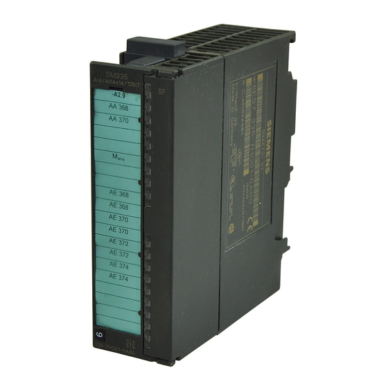
Siemens SIMATIC SM 335 Manual (109 pages)
High-speed analog mixed module
Brand:
Siemens
| Category:
I/O Systems
| Size: 1.32 MB
Table of Contents
Warning Notice System
2
Qualified Personnel
2
Proper Use of Siemens Products
2
Position in the Overall Documentation Structure
4
Other Manuals on S7-300 and ET 200M
5
Table of Contents
9
Properties of SM 335
11
Analog Inputs
11
Analog Outputs
11
Operating Modes
12
Interrupts / Diagnostics
12
Terminal Diagram of SM 335
13
Block Diagram of SM 335
14
Electrical Isolation
14
Setting up the Measuring Range Using the Measuring Range Module
15
Measuring Range Module
15
Technical Data of SM 335
16
General Technical Data of SM 335
16
Technical Data of Analog Inputs
17
Technical Data of Analog Outputs
19
Technical Data of the Interval Counter
20
Operating Modes of SM 335
21
Special Operating Modes
21
Free Cycle Mode
22
Cycle Time for the Free Cycle of SM 335
22
Conditional Cycle Mode
24
Cycle Time for the Conditional Cycle of SM 335
24
Wiring the Inputs and Outputs
25
Basics of the Wiring of SM 335
25
Rules
25
Power Supply
25
Wiring the Analog Inputs
26
Wiring Sensors
26
Non-Isolated
27
Limited Potential Difference UCM
27
Analog Inputs Which Are Not Wired
27
Wiring the Analog Outputs
28
Wiring Actuators to SM 335
28
Wiring the Interval Counter Input
29
Analog Outputs Which Are Not Wired
29
Electrically Isolated Mode
29
Wiring the Encoder Supply
30
Non-Isolated Installation
30
Example of the Encoder Supply Via SM 335
30
Adjusting the Encoder Supply
31
Voltage Value of the Encoder Supply
31
Correction Factor
31
Measured Value
31
Data Exchange with SM 335
33
Access Via I/O Addresses
34
Input Values
34
Output Values
34
Analog Values
36
Number of End of Cycle Interrupts (Modaddr + 8)
36
Return Code (Modaddr + 9)
37
Return Code of SM 335
37
Meaning of the Bits in the Return Code of SM 335
37
Meaning of Bits 0, 1 and 2 in the Return Code of SM 335
38
Representation of Analog Values of Analog Input Channels
40
Representation of Analog Values
40
Analog Value Notation in the Bipolar Input Ranges
40
Analog Value Notation in the Unipolar Input Ranges
41
Representation of Analog Values for Analog Output Channels
42
Configuring and Parameterizing
43
Default Settings of SM 335
44
SM 335 Parameters Which Can be Set up in HW Config
45
Parameters of SM 335
45
SM 335 Parameters in HW Config
45
End of Cycle Interrupt Enable
46
Diagnostics Interrupt Enable
46
Enabling Diagnostics
46
Reaction to CPU STOP
46
Modifying SM 335 Parameters in RUN
47
HW Config
47
Data Sets
47
Data Set 1 (DS31)
47
Static Parameters of SM 335
48
Data Set 0
48
Meaning of the Bits in the Byte for I/O Diagnostics
48
SM 335 Parameters for the Free and Conditional Cycle Modes
49
Output of Interrupts and Substitute Values (DS1, Byte 0)
50
Analog Input Measuring Range (DS1, Bytes 2 to 5)
51
Analog Output Range (DS1, Bytes 6 to 5)
51
Parameters for the Analog Input Measuring Range
51
Measuring Cycle Time (DS1, Byte 10)
52
Dynamic Measuring Cycle Control (DS1, Byte 11)
52
Meaning of the Bits in the " Dynamic Measuring Cycle Control" Byte
52
SM 335 Parameters for the Special Mode "Comparator"
53
Wire-Break Check
53
Meaning of the Bits in the "Wire-Break Check" Byte
53
Switchover
53
Analog Value to be Output
54
Comparator Time (DS1, Byte 1)
54
Comparator Check Byte (DS1, Byte 12)
55
Direction (DS1, Bit 12.7)
56
Comparator 1 and Comparator 2 (DS1, Bit 12.6 + 12.5)
56
PRAL (DS1, Bit 12.4)
56
Comparator 1 to Comparator 2 Switchover Point
56
SM 335 Parameters for the Special Mode "Measuring Only"
57
Data Set 1 of SM 335 for the Special Mode "Measuring Only"
57
Dynamic Measuring Cycle Control
58
Disabling Analog Inputs Dynamically
58
Evaluating the Diagnostics Data of SM 335
59
Diagnostics Interrupt
59
Hardware Interrupt
59
Local Data
60
End of Cycle Interrupt
60
Interrupt was Triggered by a Comparator
60
Structure of the Diagnostics Data for SM 335
61
Diagnostics Data of SM 335
61
Module Diagnostics Byte 0
62
External Error
63
Channel Error
63
24 V Load Voltage Missing
63
SM 335 Is Not Parameterized
63
Module Diagnostics Byte 2
64
Module Diagnostics Byte 3
64
Incorrect Measuring Range Module
64
Hardware Fault
64
EEPROM Error
65
ADC/DAC Error
65
Channel-Specific Diagnostics Bytes (Bytes 4 to 15)
65
Analog Input (Bytes 8 to 11)
66
Parameterization Error (Bytes 8 to 11, Bit 0)
66
Common Mode Error (Bytes 8 to 11, Bit 1)
66
Wire-Break (Bytes 8 to 11, Bit 4)
66
Analog Output (Bytes 12 to 15)
67
Channel-Specific Diagnostics Byte for the Analog Output
67
Interval Counter Input
69
Principle of an Interval Counter
69
Interval Counter
70
Interval Duration Counter
70
Simple Encoder, E.g. Slotted Disk on a Shaft
70
Principle of Measurement with the Interval Counter
71
Lower Limit
71
Upper Limit
72
Limits for Different Pulse Rates N
72
Wiring the Encoder to the Interval Counter Input
72
Current
73
Switch
73
Grounding
73
Parameterizing the Interval Counter Input of SM 335
74
Monitoring Time
74
Values of the Interval Counter
75
Address
75
Interval Counter (Modaddr + 12)
75
Interval Counter (Modaddr + 13...15)
75
Example of a Speed Calculation Using the Interval Counter
76
Requirements
76
Calculating the Interval Duration
76
Calculating the Speed
76
Special Operating Modes of SM 335
77
Comparator
77
Measuring Only
77
Switchover to the Special Operating Modes
78
Comparator (DS1, Byte 11)
78
Measuring Only (DS1, Byte 11)
78
Special Operating Mode "Comparator"
79
Definition of a Comparator
79
Two Comparators
79
Principle of the Special Operating Mode "Comparator"
80
Three Options
80
Comparator 1
80
Operating Principle of Comparator 1
80
Operating Principle of Comparator 2
81
Case A: Reference Value Reached
82
Case B: Comparator Time Expired
82
Reaction for Case a and B
82
Comparator 1 and 2
83
Operation with Comparator 2
83
Application
84
Application for the Special Operating Mode "Comparator"
84
Restriction
85
Comparator Time (DS1, Byte 10)
85
Data Set 1 of SM 335 for the Special Mode "Comparator"
85
Analog Output (DS1, Bits 12.3 to 12.0)
87
Comparator 1 and Comparator 2 (DS1, Bits 12.6 to 12.5)
87
Measured Value Comparator 2
87
Special "Measuring Only" Mode
88
Disabling Outputs
88
Changing over to the Special Operating Mode "Measuring Only"
89
Enabling an Operating Mode
90
Troubleshooting
91
Principle of Diagnostics
91
Parameterizing Diagnostics
91
Diagnostics Buffer
91
Setting up Diagnostics in HW Config
92
Disadvantage of the Diagnostics Interrupt
92
Diagnostics Messages of SM 335
92
Measuring Range 0 to 10 V
93
Evaluating Diagnostics Data in ob 82
94
Error Tree of SM 335
95
Reading Help
95
Faults and Troubleshooting on SM 335
96
List of Abbreviations
99
Glossary
101
2-/3-/4-Wire Connection
101
Index
107
Advertisement
Siemens SIMATIC SM 335 Manual (118 pages)
High-Speed Analog Input/Output Module for the SIMATIC S7-300
Brand:
Siemens
| Category:
I/O Systems
| Size: 0.54 MB
Table of Contents
Table of Contents
9
Contents
2
The SIMATIC S7
3
Specifications of the SM
6
Table of Contents
9
1 Characteristics and Technical Specifications of the SM 335
11
Characteristics Features of the SM 335
12
Terminal Connection Diagram for the SM 335
13
Block Diagram of the SM 335
15
Setting the Measuring Range with the Measuring Range Module
16
Technical Specifications for the SM 335
17
Technical Specifications for the Analog Inputs
18
Technical Specifications for the Analog Outputs
20
Technical Specifications for the Interval Counter
21
SM 335 Operating Modes
23
Conditional Cycle Mode
26
2 Connecting the Inputs and Outputs of the Sm 335
27
Connecting the Inputs and Outputs of the SM 335
28
Basic Information about Connecting the SM
28
Connecting the Analog Inputs
29
Connecting the Analog Outputs
31
Connecting the Interval Counter Input
32
Connecting the Sensor Power Supply
33
Correcting the Sensor Power Supply
35
Interference Suppression Filter for 24 V Supply Voltage
36
3 Data Exchange with the SM 335
39
Access Via the I/O Addresses
41
Output Values
45
Analog Value Representation for Analog Input Channels
46
Analog Value Representation for Analog Output Channels
48
Setting Parameters Via HW Config
49
SM 335 Default Settings
50
SM 335 Parameters Assignable with HW Config
51
Modifying SM 335 Parameters with the Help of System Function 55
54
SM 335 Static Parameters
55
SM 335 Parameters in the Free Cycle and Conditional Cycle Modes
56
Table of Contents
60
SM 335 Parameter for "Comparator" Mode
61
SM 335 Parameters for "Measuring Only" Special Mode
65
Analog Input CH3
66
Analog Input CH0
66
Evaluating SM 335 Diagnostics
67
Hardware Interrupt
68
Format of Diagnostic Data for the SM 335
70
Module Diagnostic Byte 1 (Byte 0)
71
Module Diagnostic Byte 2 (Byte 1)
73
Module Diagnostic Byte 4 (Byte 3)
74
Channel-Specific Diagnostic Bytes (Bytes 4-15)
75
Fig
66
Analog Input CH1
66
Analog Input CH2
66
4 Interval Counter Input
77
Principle of an Interval Counter
78
Principles of Measuring with the Interval Counter
79
Wiring the Interval Counter Input
81
Initializing the SM 335'S Interval Counter Input
83
Interval Counter Values
84
Example for Determining the Speed by Means of the Interval Counter
85
5 Special SM 335 Operating Modes
87
Switching to the Special Operating Modes
88
Comparator" Mode
89
How Comparator Mode Works
90
SM 335 Parameters for Comparator Mode
96
Measuring Only" Mode
100
Switching to "Measuring Only" Mode
101
6 Detecting and Correcting Faults
103
Principle of Diagnostics
104
Configuring Diagnostics with HW Config
106
Evaluating Diagnostic Data in ob 82
108
SM 335 Error Tree
109
Troubleshooting
110
Index
115
Advertisement
Related Products
Siemens SIMATIC S5 CP 523
Siemens Simantic ET200SP
Siemens Simantic ET 200S
Siemens SIMATIC S7 EIP-200S
Siemens Simatic CFU
Siemens SICAM AI
Siemens S55376-C104
Siemens SIMATIC PM-E
Siemens S7-I/O
Siemens SIMATIC 6ES7134-4FB01-0AB0
Siemens Categories
Industrial Equipment
Controller
Control Unit
Oven
Washer
More Siemens Manuals
Login
Sign In
OR
Sign in with Facebook
Sign in with Google
Upload manual
Upload from disk
Upload from URL