Sign In
Upload
Manuals
Brands
Siemens Manuals
Engine
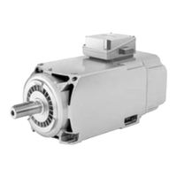
SIMOTICS M-1PH828
Siemens SIMOTICS M-1PH828 Manuals
Manuals and User Guides for Siemens SIMOTICS M-1PH828. We have
1
Siemens SIMOTICS M-1PH828 manual available for free PDF download: Operating And Installation Instructions
Siemens SIMOTICS M-1PH828 Operating And Installation Instructions (314 pages)
Main motors
Brand:
Siemens
| Category:
Engine
| Size: 17.5 MB
Table of Contents
Edition
4
Table of Contents
5
Disposal
13
Introduction
13
Information for the Nominated Person in Control of the Electrical Installation
15
Safety Information
15
The Five Safety Rules
15
Qualified Personnel
16
Safe Handling
16
Electrostatic Sensitive Devices
18
Interference Immunity
19
Interference Voltages When Operating the Converter
19
Electromagnetic Fields When Operating Electrical Power Engineering Installations
20
Description
21
Figure 3-1 Schematic Layout of Rating Plate
21
Table 3-1 Elements on the Rating Plate
22
Table 3-2 Machine Design
23
Table 3-3 Technical Data of the Holding Brake
26
Table 3-4 Roller Bearing Versions
27
Table 4-1 Cooling Water Specification
29
Ensuring Cooling
30
Figure 4-1 Air Guidance from the de to the NDE (Schematic Representation, Types 1PH818. and 1PH822.)
31
Figure 4-2 Bypass for 1PH822. for IP23
32
Figure 4-3 Air Guidance from the NDE to the de (Schematic Representation, Type 1PH828.) for IP55
32
Table 4-2 Pressure Drop in Motors with Pipe Connection
33
Noise Emissions
34
Overheating During Periodic Duty
34
Thermal Motor Protection
34
Rotational Speed Limit Values
35
System-Inherent Frequencies
35
Torsional Loading of the Drive Train Due to Faults in the Electrical Supply
35
Checking the Delivery
36
Lifting and Transportation
36
Transport and Storage
36
Figure 4-4 Lifting the Machine (Schematic Representation)
38
Figure 4-5 Rotor Shipping Brace
39
Table 4-3 Tightening Torque and Preloading Force for Axially Fixing the Rotor
39
Transporting a Force-Ventilated Motor that Has Already Been in Operation
40
Transporting a Water-Cooled Motor that Has Already Been in Operation
40
Storage
41
Transporting the Machine Set
41
Attaching the Rotor Shipping Brace Prior to Storage
43
Protect the Cooling Water System of Water-Cooled Motors
44
Protection against Corrosion
45
Figure 4-6 Schematic Representation of a Single Drive
46
Insulated Bearings for Converter Operation
46
Preparing for Installation
49
Interlock Circuit for Anti-Condensation Heating (Option)
33
Interlock Circuit for the External Fan
33
Cooling Water Quality for Water-Cooled Motors
29
Observing the Operating Mode
29
Preparations for Use
29
Safety-Related Aspects to Consider When Configuring the Plant
29
Insulation Resistance and Polarization Index
50
Table 5-1 Stator Winding Insulation Resistance at 40° C
51
Prepare the Mounting Surfaces (IM B3)
53
Figure 5-1 Balancing Type on the Drive-End Side
54
Removing Anti-Corrosion Protection
54
Lifting and Transporting the Machine
56
Open the Condensation Water Drain Holes (Water-Cooled Motor)
57
Figure 5-2 Water Drain Holes
58
Figure 5-3 Water Drain Holes, for Types 1PH818., 1PH822
58
Aligning to the Driven Machine
62
Figure 5-4 Max. Permissible Vibration Velocity, Taking into Account the Vibration Displacement and
62
Figure 5-5 Aligning the Motor
63
Mounting the Motor
64
Refitting the External Fan
65
Electrical Connection
67
Figure 6-1 Terminal Lug for the Grounding Conductor for a Force-Ventilated Motor
68
Preparation
68
① for the Grounding Conductor for a Force-Ventilated Motor
68
Connecting
69
Figure 6-2 Terminal Lug for the Grounding Conductor for a Water-Cooled Motor
69
① for the Grounding Conductor for a Water-Cooled Motor
69
Laying Cables
70
Connection with Cable Lugs
71
Connecting Aluminum Conductors
73
Performing Connection Operations
74
Auxiliary Circuits
75
Connecting an EC External Fan
77
Figure 6-3 External Fan Terminal Box (Schematic Representation)
77
① (Schematic Representation)
77
Connecting an External Fan with Three-Phase Motor (Option L75)
78
Figure 6-4 External Fan Terminal Box (Schematic Representation)
78
Supply Values for External Fans with Three-Phase Motor (Option L75)
79
Attached Air Discharge Throttle Plate (Option L75)
80
Open Condensation Drain Holes (Air-Cooled Motor, L12)
58
Putting the Machine down
59
Installing the Machine
60
Preconditions for Smooth, Vibration-Free Operation
61
Vibration Acceleration
62
Figure 6-5 Throttle Plate for Suction-Type Ventilation (de to NDE)
81
Figure 6-6 Throttle Plate for Forced-Draft Ventilation (NDE to DE)
81
Connecting the Speed Encoder
82
Figure 6-7 Detailed View: Plug-In Connection
82
Connect the Holding Brake
83
Figure 6-8 Sensor Module Mounted on the Terminal Box
83
Connecting to a Converter
84
Converter Operation on a Grounded Network
85
Commissioning
87
Insulation Resistance and Polarization Index
88
Checks to be Carried out Prior to Commissioning
89
Perform a Test Run with the Water-Cooled Motor
91
Test Run
92
Set Values for Monitoring the Bearing Temperature (Optional)
93
Safety Guidelines in Operation
95
Do Not Operate Water-Cooled Motors Without Cooling Water
97
Switching off Water-Cooled Motors
98
Avoidance of Damage to Roller Bearings During Stop
99
Re-Commissioning the Machine
100
Electrical Faults at Water-Cooled Motors
101
Mechanical Faults
102
Roller Bearing Faults
103
Observe the Operating Instructions of the Components
105
Inspection and Maintenance
106
Inspections in the Event of Faults
107
Main Inspection
108
Regreasing Intervals
109
Maintenance Intervals
110
Table 9-4 Criteria for Selecting Roller Bearing Greases
111
Figure 9-1 Flat Grease Nipples and , Schematic Representation for Types 1PH818. and 1PH822
115
Cleaning the Spent Grease Chamber
116
Figure 9-2 Flat Grease Nipple and (Schematic Representation for Type 1PH828.)
116
Figure 9-3 Fitting the Protecting Ring
123
Removing and Mounting the Bearing Shields
123
Figure 9-4 Sealing Gap between the Enclosure and Bearing Shields (Schematic Representation)
125
Sealing the Motor (Type 1PH828.)
125
Figure 9-5 Installing the Rotary Shaft Seal
126
Relocating the External Fan (Type 1PH828.)
126
① and ② (Schematic Representation for Type 1PH828.)
116
Servicing the External Fan
117
Maintaining Terminal Boxes
118
Repair
119
Screws with Precote Coating
120
Dissembling a Force-Ventilated Motor
121
Removing and Installing the Protecting Ring
122
① and ② , Schematic Representation for Types 1PH818. and 1PH822
115
Figure 9-6 Unscrewing the External Fan (1PH818., 1PH822.)
127
Figure 9-7 Unscrewing the External Fan (1PH828.)
127
Figure 9-8 Detailed View of the Speed Encoder
128
Removing and Mounting the Speed Sensor
128
Connecting the Speed Encoder
130
Touch up any Damaged Paintwork
131
Ordering Data
133
Holding Brake
134
Water-Cooled Motor
135
Roller Bearing Cartridge de with Radial Shaft Sealing Ring with Regreasing
136
Rolling-Contact Bearing Bush Drive End, Belt Coupling
137
Rolling-Contact Bearing Bush Drive End, Coupling Output, with Regreasing
138
Rolling-Contact Bearing Bush Drive End, Coupling Output, with Permanent Lubrication
139
Rolling-Contact Bearing Bush Non-Drive End, with Permanent Lubrication
140
Roller Bearing Cartridge NDE, with Regreasing (Type 1PH818., 1PH822.)
141
Roller Bearing Cartridge NDE, with Regreasing (Type 1PH828.)
142
Rolling-Contact Bearing Bush Non-Drive End "Performance
143
Force-Ventilated Motor
144
External Fan
145
Roller Bearing Cartridge de with Radial Shaft Sealing Ring with Regreasing
146
Roller Bearing Cartridge DE, Belt Coupling
147
Roller Bearing Cartridge DE, Coupling Output, with Regreasing
148
Roller Bearing Cartridge DE, Coupling Output, with Permanent Lubrication
149
Roller Bearing Cartridge NDE, with Permanent Lubrication
150
Roller Bearing Cartridge NDE, with Regreasing (Type 1PH818., 1PH822.)
151
Roller Bearing Cartridge NDE, with Regreasing (Type 1PH828.)
152
Roller Bearing Cartridge NDE, "Performance
153
Terminal Box
154
Speed Encoder (Type 1PH818., 1PH822.)
155
Speed Encoder (Type 1PH828.)
156
Disposal
157
Preparing for Disassembly
157
Rohs - Restricting the Use of Certain Hazardous Substances
157
Dismantling the Machine
158
Disposal of Components
158
Service and Support
161
Technical Specifications
163
Tightening Torques for Screw and Bolt Connections
163
Quality Documents
165
Additional Documents
167
Reader Notes on the Operating Instructions of the Holding Brake
167
Operating Instructions, Holding Brake
169
Operating Instructions for the Single-Phase EC External Fan, Suction, SH180
193
Operating Instructions for the Single-Phase EC External Fan, Suction, SH225
207
Operating Instructions for the Single-Phase EC External Fan, Pressing, SH180
221
Operating Instructions for the Single-Phase EC External Fan, Pressing, SH225
235
Operating Instructions for the Three-Phase EC External Fan, Suction, SK180
249
Operating Instructions for the Three-Phase EC External Fan, Suction, SK225
263
Operating Instructions for the Three-Phase EC External Fan, Pressing, SH180
279
Operating Instructions for the Three-Phase EC External Fan, Pressing, SH225
293
Index
309
Advertisement
Advertisement
Related Products
Siemens SIMOTICS M-1PH818
Siemens SIMOTICS M-1PH822
Siemens SIMOTICS M-1PH8
Siemens SIMOTICS M-1PH808
Siemens SIMOTICS M-1PH810
Siemens SIMOTICS M-1PH1
Siemens SIMOTICS M-1PH3
Siemens Simotics M-1FE1 Series
Siemens SIMOTICS M-1FE2
Siemens MICROMASTER MI220/3
Siemens Categories
Industrial Equipment
Controller
Control Unit
Oven
Washer
More Siemens Manuals
Login
Sign In
OR
Sign in with Facebook
Sign in with Google
Upload manual
Upload from disk
Upload from URL