Sign In
Upload
Manuals
Brands
Siemens Manuals
Valve Positioners
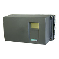
SIPART PS2 6DR51 Series
Siemens SIPART PS2 6DR51 Series Manuals
Manuals and User Guides for Siemens SIPART PS2 6DR51 Series. We have
2
Siemens SIPART PS2 6DR51 Series manuals available for free PDF download: Operating Instructions Manual, Manual
Siemens SIPART PS2 6DR51 Series Operating Instructions Manual (336 pages)
Electropneumatic positioners with 4 to 20 mA/HART
Brand:
Siemens
| Category:
Valve Positioners
| Size: 12.38 MB
Table of Contents
Table of Contents
3
1 Introduction
13
Purpose of this Documentation
13
Scope of Documentation
13
Document History
14
Designated Use
15
Product Compatibility
15
Checking the Consignment
16
Security Information
16
Transportation and Storage
17
Notes on Warranty
17
2 Safety Information
19
Precondition for Use
19
Warning Symbols on the Device
19
Laws and Directives
19
Conformity with European Directives
20
Product Approval and UL Compliance
20
Improper Device Modifications
20
Improper Modification on Positioner 6DR5
21
Requirements for Special Applications
21
Use in Hazardous Areas
22
3 Description
23
Function
23
Structure
23
Overview of Structure
23
Nameplate Layout
26
Explanation of Ex Information
27
Device Components
28
Overview of Device Components
28
Basic Electronics
29
Mode of Operation
30
Block Circuit Diagram for Single-Acting or Double-Acting Actuators
32
Mode of Operation of the HART Function
33
HART System Configuration
33
Simatic Pdm
34
4 Installing/Mounting
37
Basic Safety Instructions
37
Proper Mounting
39
Loss of Explosion Protection
39
Mounting to Linear Actuator
40
Mounting to Part-Turn Actuator
45
Setting and Locking the Transmission Ratio
48
Installing Option Modules
51
General Information on Installing Option Modules
51
Opening the Standard and Intrinsically Safe Version
52
Closing the Standard and and Intrinsically Safe Version
53
Opening the Device Version with "Flameproof Enclosure
55
Closing the Device Version with "Flameproof Enclosure
58
Digital I/O Module (DIO) 6DR4004-6A / -8A
59
Analog Output Module (AOM) 6DR4004-6J / -8J
60
Inductive Limit Switches (ILS) 6DR4004 6G / -8G
62
Inductive Limit Switches (ILS) - Mode of Operation and Equipment Features
62
Installation Procedure for Inductive Limit Switches (ILS)
63
Setting Limits
64
Mechanic Limit Switches (MLS) 6DR4004-6K / -8K
65
Mechanic Limit Switches (MLS) - Mode of Operation and Equipment Features
65
Installation Procedure for Mechanic Limit Switches (MLS)
66
Setting Limits
67
Internal NCS Module (Incs) 6DR4004-5L / -5LE
68
Analog Input Module (AIM) 6DR4004-6F / -8F
71
5 Connection
75
Basic Safety Instructions
75
Electrical Wiring
79
Connection Diagram for Basic Electronics
79
Connection Diagram Split Range
82
Option Modules
83
Digital I/O Module (DIO) 6DR4004-6A / -8A
83
Analog Output Module (AOM) 6DR4004-6J / -8J
84
Inductive Limit Switches (ILS) 6DR4004-6G / -8G
84
Mechanical Limit Switches (MLS) 6DR4004-6K / -8K
85
Analog Input Module (AIM) 6DR4004-6F / -8F
87
Optional Version M12 Device Plug
88
In the Basic Unit
88
In the Basic Unit with Analog Output Module (AOM) 6DR4004-6J/-8J (-Z D53)
89
In the Basic Unit with Position Transmitter (-Z D54)
89
In the Basic Unit with Digital I/O Module (DIO) 6DR4004-6A/-8A (-Z D55)
89
In the Basic Unit with Inductive Limit Switches (ILS) 6DR4004-6G/-8G (-Z D56)
90
In the Basic Unit with Mechanic Limit Switches (MLS) 6DR4004-6K (-Z D57)
90
Pneumatic Connection
90
Basic Safety Instructions for the Pneumatic Connection
90
Pneumatic Connection in Non-Flameproof Enclosure
91
Structure of Pneumatic Connection
91
Integrated Pneumatic Connection
91
Pneumatic Connection in the Flameproof Enclosure
92
Behavior in Case of Failure of the Electrical Auxiliary Power And/Or the Supply Pressure PZ
93
Restrictors
93
6 Operating
95
Operating Elements
95
Display
95
Buttons
96
Firmware Version
97
Operating Modes
98
Overview of Operating Modes
98
Changing the Operating Mode
98
Overview of Configuration
99
Description of Operating Modes
99
Optimization of Controller Data
101
7 Commissioning
105
Basic Safety Instructions
105
Overview
107
Sequence of Automatic Initialization
109
RUN 1 Sequence
110
RUN 2 Sequence with Linear Actuators
111
RUN 2 Sequence with Part-Turn Actuators
112
RUN 3 to 5 Sequence
113
Setting the Friction Clutch
115
Purge Air Switching
117
Commissioning Linear Actuators
117
Preparing Linear Actuators for Commissioning
117
Automatic Initialization of Linear Actuators
119
Manual Initialization of Linear Actuators
121
Commissioning Part-Turn Actuators
124
Preparing Part-Turn Actuators for Commissioning
124
Automatic Initialization of Part-Turn Actuators
125
Manual Initialization of Part-Turn Actuators
126
Canceling Initialization
129
Device Replacement
129
8 Parameter Assignment
133
Introduction to Parameter Assignment Section
133
Configuration Schematic for Parameter Operating Principle
134
Tabular Overview of the Parameters
135
Overview of Initialization Parameters 1 to 5
135
Overview of Application Parameters 6 to 52
136
Overview of Advanced Diagnostic Parameters a to U
139
Overview Parameter J
142
Description of Parameters
143
Initialization Parameters 1 to 5
143
YFCT' Type of Actuator
143
YAGL' Rated Angle of Rotation of Feedback
145
YWAY' Range of Stroke
145
INITA' Initialization (Automatic)
146
INITM' Initialization (Manual)
146
Application Parameters 6 to 52
147
SCUR' Current Range of Setpoint
147
SDIR' Setpoint Direction
147
SPRA' Setpoint Split Range Start / '9.SPRE' Setpoint Split Range Start End
147
TSUP' Setpoint Ramp up / '11.TSDO' Setpoint Ramp down
148
SFCT' Setpoint Function
149
Sl0
149
DEBA' Deadband of Closed-Loop Controller
150
YA' Start of Manipulated Variable Limit / '36.YE' End of Manipulated Variable Limit
151
YNRM' Standardization of Manipulated Variable
151
YCLS' Tight Closing/Fast Closing with Manipulated Variable
153
YDIR' Direction of Manipulated Variable for Display and Position Feedback
153
YCDO' Value for Tight Closing/Fast Closing down
154
YCUP' Value for Tight Closing/Fast Closing up
154
BIN1' / '43.BIN2' Digital Input Function
155
AFCT' Alarm Function
156
A1' / '46.A2' Response Threshold of Alarm
158
FCT' Function of the Fault Message Output
158
LIM' Response Threshold of Fault Message 'Control Deviation
159
TIM' Monitoring Period for Setting of Fault Message 'Control Deviation
159
PNEUM' Pneumatics Type
160
PRST' Preset
160
XDIAG' Activating for Extended Diagnostics
162
Advanced Diagnostic Parameters a to U
163
Partial Stroke Test 'A.\\PST
163
Monitoring of Dynamic Control Valve Behavior 'B.\\Devi
168
Monitoring/Compensation of Pneumatic Leakage 'C.\\LEAK
170
Monitoring of Stiction (Slipstick) 'D.\\Stic
173
Monitoring of Deadband 'E.\\DEBA
175
Monitoring of Lower Endstop 'F.\\ZERO
176
Monitoring the Upper Endstop 'G.\\OPEN
177
Monitoring the Lower Limit Temperature 'H.\\TMIN
179
J2.LEVL1 - Threshold 1
181
Monitoring the Upper Limit Temperature 'J.\\TMAX
181
J3.LEVL2 - Threshold 2
182
J4.LEVL3 Threshold 3 -40
182
Monitoring of Number of Total Strokes 'L.\\STRK
182
L1. LIMIT Limit 1
183
L2.FACT1 - Factor 1
183
L3.FACT2 Factor 2 0.1
183
L4.FACT3 Factor 3 0.1
183
Monitoring of Number of Changes in Direction 'O.\\DCHG
184
O1.LIMIT Limit 1
184
O2.FACT1 Factor 1 0.1
184
Monitoring the Position Average Value 'P.\\PAVG
185
O3.FACT2 - Factor 2
185
O4.FACT3 Factor 3 0.1
185
P3.LEVL1 - Threshold 1
187
P4.LEVL2 Threshold 2 0.1
187
P5.LEVL3 Threshold 3 0.1
187
Pressure Monitoring 'U.\\PRES
188
Overview of the Assignment of the HART Variables
189
9 Functional Safety
191
Range of Applications for Functional Safety
191
Safety Function
191
Safety Integrity Level (SIL)
193
Settings
194
Safety Characteristics
195
Maintenance/Check
195
10 Service and Maintenance
197
Basic Safety Instructions
197
Maintenance
197
Cleaning
198
Positioners 6DR5..0, 6DR5..3 and 6DR5..5
198
Positioners 6DR5..1, 6DR5..2 and 6DR5..6
199
Maintenance and Repair Work
199
Replace Basic Electronics
200
Replace Pneumatic Block
202
Replace the Pressure Sensor Module
203
Return Procedure
206
Disposal
206
11 Diagnostics and Troubleshooting
207
Output of System Messages in the Display
207
System Messages before Initialization
207
System Messages During Initialization
207
System Messages When Exiting the Configuration Mode
210
System Messages During Operation
210
Diagnostics
212
Display of Diagnostics Values
212
Saving the Diagnostics Values
212
Overview of Diagnostics Values
213
Meaning of the Diagnostics Values
215
Diagnostic Value '1.STRKS - Number of Total Strokes
215
Diagnostic Value '2.CHDIR - Number of Changes in Direction
215
Diagnostic Value '3.\\CNT - Number of Fault Messages
215
Diagnostic Value '4.A1CNT - Number of Alarms 1' / '5.A2CNT - Number of Alarms 2
215
Diagnostic Value '6.HOURS - Number of Operating Hours
216
Diagnostic Value '7.HOURR - Resettable Operating Hours Counter
216
Diagnostic Value '8.WAY - Determined Travel
216
Diagnostic Value '9.TUP - Travel Time Up' / '10.TDOWN - Travel Time down
216
Diagnostic Value '11.LEAK - Leakage Test
217
Diagnostic Value '12.PST - Monitoring of Partial Stroke Test
218
Diagnostic Value '13.PRPST' - Time Since Last Partial Stroke Test
219
Diagnostic Value '13.PRPST - Time Since Last Partial Stroke Test' (Version with Pressure Sensor Module)
219
Diagnostic Value '14.NXPST - Time until Next Partial Stroke Test
219
Diagnostics Value '15.DEVI - Dynamic Control Valve Behavior
220
Diagnostic Value '16.ONLK - Pneumatic Leakage
220
Diagnostic Value '17.STIC - Stiction (Slipstick)
220
Diagnostic Value '18.ZERO - Lower Endstop
220
Diagnostic Value '19.OPEN - Upper Endstop
221
Diagnostic Value '20.PAVG - Average Value of Position
221
Diagnostic Value '21.P0 - Potentiometer Value of Lower Endstop (0%)' / '22.P100 - Potentiometer Value of Upper Endstop (100%)
221
Diagnostic Value '23.IMPUP - Pulse Length Up' / '24.IMPDN - Pulse Length down
223
Diagnostic Value '25.PAUTP - Pulse Interval
223
Diagnostic Value '26.DBUP - Deadband Up' / '27.DBDN - Deadband down
223
Diagnostic Value '28.SSUP - Slow Step Zone Up' / '29.SSDN - Slow Step Zone down
224
Diagnostic Value '30.TEMP - Current Temperature
224
Diagnostic Value '31.TMIN - Minimum Temperature' / '32.TMAX - Maximum Temperature
224
Diagnostic Value '33.T1
225
Diagnostic Value '42.VENT1' / '43.VENT2
225
Diagnostic Value '44.VEN1R' / '45.VEN2R
225
Diagnostic Value '46.STORE - Save Maintenance Data
226
Diagnostic Value '47.PRUP - Prediction Up' / '48.PRDN - Prediction down
226
Diagnostic Value '49.WT00
227
WT00 to WT95
227
Diagnostic Value '57.LKPUL - Length of the Leakage Compensation Pulse
227
Diagnostic Value '58.LKPER - Period of the Leakage Compensation Pulse
227
Diagnostic Value '59.Ma - Setpoint Current
228
Diagnostic Value '60.PZ Supply Pressure (PZ)
228
Diagnostic Value '63.PZMAX Supply Pressure (PZ) Min/Max Pointer
228
Diagnostic Value '64.N_MIN Event Counter
228
Online Diagnostics
229
Overview of Error Codes
229
Overview of Online Diagnostics
231
XDIAG Parameter
231
Meaning of Error Codes
232
Remaining Control Deviation
232
Device Not in "Automatic" Mode
232
Digital Inputs BIN1 or BIN2 Active
232
Monitoring the Number of Total Strokes
232
Monitoring the Number of Changes in Direction
232
Monitoring the Lower Endstop / 7 Monitoring the Upper Endstop
232
Monitoring Deadband
233
Partial Stroke Test
233
Monitoring of Dynamic Control Valve Behavior
233
Monitoring/Compensation of Pneumatic Leakage
234
Monitoring of Stiction (Slipstick)
234
Monitoring the Lower Limit Temperature
234
Monitoring the Upper Limit Temperature
234
Monitoring the Position Average Value
234
Monitoring the Plausibility of Values for the Partial Stroke Test
234
Monitoring of Pressure Sensor Module
234
Monitoring Low Limit of Supply Pressure (PZLIM)
234
Monitoring Specific Limits of Supply Pressure
234
Fault and Remedy
235
12 Technical Data
239
HART Operating Conditions
239
Pneumatic Data
239
Construction
240
Controller
242
Certificates and Approvals
243
Breakdown of the Article Numbers
243
Basic Unit and Optional Modules
244
Maximal Permissible Ambient Temperature Ranges
245
Electrical Data
246
Electrical Data for Pressure Sensor Module
248
Communication (HART)
248
Technical Data for Natural Gas as Actuator Medium
249
Option Modules
250
Digital I/O Module (DIO) 6DR4004-6A / -8A
250
Analog Output Module (AOM) 6DR4004-6J / -8J
251
Inductive Limit Switches (ILS) 6DR4004-6G / -8G
252
Mechanic Limit Switches (MLS) 6DR4004-6K / -8K
253
Analog Input Module (AIM) 6DR4004-6F / -8F
254
Internal NCS Module 6DR4004-5L / 6DR4004-5LE
254
Other Technical Specifications
255
13 Dimension Drawings
257
Positioner in Non-Flameproof Enclosure
257
Terminal Strip for Enclosures 6DR5..0 and 6DR5..3
258
Positioner in Flameproof Enclosure
259
14 Spare Parts/Accessories/Scope of Delivery
261
Overview
261
Spare Parts
263
Scope of Delivery Mechanic Limit Switches (MLS)
266
Scope of Delivery Analog Input Module (AIM)
267
Accessories
268
Order Data
268
Product Documentation and Support
269
Product Documentation
269
Technical Support
270
External Position Detection
271
Introduction
271
Non-Contacting Sensor
272
Principle of Operation of NCS
272
Mounting the NCS
273
Mounting on Part-Turn Actuator
274
Mounting on Linear Actuator up to 14 MM (0.55 Inch)
276
Mounting on Linear Actuator > 14 MM (0.55 Inch)
278
Connecting NCS to Analog Input Module (AIM)
281
Commissioning of NCS
282
Prerequisites / Default Settings
282
Initialization of Part-Turn Actuators
283
Initializing Linear Actuators with a Stroke Range up to 14 MM (0.55 Inch)
283
Initializing Linear Actuators with a Stroke Range > 14 MM (0.55 Inch)
283
Technical Specifications NCS
283
Dimensional Drawing of Non-Contacting Sensor
285
NCS Sensor Scope of Delivery
285
Scope of Delivery of NCS for Part-Turn Actuators
285
Scope of Delivery of NCS for Linear Actuators up to 14 MM (0.55 Inch)
286
Scope of Delivery of NCS for Linear Actuators > 14 MM (0.55 Inch)
287
External Position Detection
288
Mode of Operation for External Position Detection
288
Installation of External Position Detection System
288
Connecting to Analog Input Module (AIM)
289
Technical Specifications of the External Position Detection System
289
Rated Conditions for External Position Detection
289
Electrical Data for External Position Detection
289
Pressure Gauge Block
295
Sealing Plug / Thread Adapter
297
Intended Use of Accessory Part
297
Safety Instructions for Accessory Part
297
Technical Specifications of Accessory Part
298
Dimensional Drawings for Accessory Part
299
Booster
301
Booster Introduction
301
Mounting a Booster
301
Booster Commissioning
305
Booster Dimension Drawings
308
For Positioners in Non-Flameproof Enclosure
308
For Positioners in Flameproof Enclosure
309
Technical Specifications of Booster
309
Positioner with Remote Control Electronics
311
Introduction to Remote Control Electronics
311
19" Slide-In Module
311
Description of 19" Slide-In Module 4 to 20 Ma
311
Connecting the 19" Slide-In Module 4 to 20 Ma
312
Grounding Concept of 19" Slide-In Module 4 to 20 Ma
312
Electrical Connection of 19" Slide-In Module 4 to 20 Ma
314
Technical Specifications of 19" Slide-In Module 4 to 20 Ma
316
Dimensional Drawing of 19" Slide-In Module 4 to 20 Ma
318
Scope of Delivery of Remote Control Electronics
318
Positioner Without Basic Electronics 6DR5910
318
Abbreviations
321
Abbreviations for Positioners
321
Abbreviations for Functional Safety
322
Glossary
325
Index
333
Advertisement
Siemens SIPART PS2 6DR51 Series Manual (160 pages)
Electropneumatic Positioner for Linear and Part-Turn Actuators
Brand:
Siemens
| Category:
Valve Positioners
| Size: 4.81 MB
Table of Contents
Table of Contents
3
Information for the Operator
5
General Information
5
A5E00074630
6
Qualified Personnel
7
Use as Intended
9
Technical Documentation
9
Warranty Information
9
Delivery Notes
10
Standards and Regulations
10
Classification of Safety Related Notices
6
1 Introduction
11
General Information about the Positioner
11
Single/Double-Acting
13
2 Design and Method of Operation
15
Overview
15
Design Name Plate
17
Instrument Components
17
Motherboard
18
Electrical Connections
18
Pneumatic Connections
19
Mounting Kit
22
Purge Air Switching (Not in the Explosion Proof Version)
22
Restrictors
22
Method of Operation
23
HART-Function
26
State as Supplied
26
Installation of Options Modules
27
Installation of Options Modules in Normal and Intrinsically Safe Versions
27
Installation of Options Modules in Explosion Proof Version
29
Iy-Module
31
Alarm Module
32
SIA Module
33
Mechanical Limit Switch Module
35
EMC Filter Module
38
Accessories
39
3 Preparing for Operation
41
Instrument Identification (Type Key)
41
Dimensional Drawings
41
Assembly
43
Instructions for Using Positioners in a Wet Environment
44
Instructions for Using Positioners Which Are Exposed to Strong Accelerations or Vibrations
46
Mounting Kit "Linear Actuator" 6DR4004-8V and 6DR4004-8L
49
Assembly Procedure (See Figure
50
Mounting Kit "Part-Turn Actuator" 6DR4004-8D
52
Assembly Procedure (See Figure 3-8 and Figure 3-9)
53
Electrical Connection
57
Connection in Non-Intrinsically Safe and Explosion Proof Version
59
Connection in Intrinsically Safe Version
62
Mechnical Limit Switch Module
67
Connection in Type of Protection "N" Version
68
Pneumatic Connection
71
Commissioning
72
Automatic Initialization
72
Preparations for Linear Actuators
73
Automatic Initialization of Linear Actuator
74
Manual Initialization of Linear Actuator
76
Preparations for Part-Turn Actuator
79
Automatic Initialization of Part-Turn Actuator
79
Manual Initialization of Part-Turn Actuators
81
Automatic Initialization (Structograms)
82
Copying Initialization Data (Positioner Exchange)
87
4 Operation
89
Display
89
Input Keys
89
Operating Modes
92
Parameters
95
Diagnostics
122
Diagnostic Display
122
Meaning of the Diagnostic Values
123
Online Diagnostics
131
Fault Correction
136
Meaning of the Other Display Text
139
Optimizing the Controller Data
143
5 Service and Maintenance
145
6 Technical Data
147
7 Scope of Delivery
153
Scope of Delivery of Standard Controller
154
Scope of Delivery of Options
154
Scope of Delivery of Accessories
155
List of Spare Parts
156
8 Index
157
Literature and Catalogs
159
9 Appendix
160
Advertisement
Related Products
Siemens SIPART PS2 6DR51xx
Siemens SIPART PS2 6DR5110 Series
Siemens SIPART PS2 6DR5120 Series
Siemens SIPART PS2 6DR5111 Series
Siemens SIPART PS2 6DR50xx
Siemens SIPART PS2 6DR52xx
Siemens SIPART PS2 6DR52 Series
Siemens SIPART PS2 6DR5xx5 series
Siemens SIPART PS2 6DR5020 Series
Siemens SIPART PS2 6DR5215 Series
Siemens Categories
Industrial Equipment
Controller
Control Unit
Oven
Washer
More Siemens Manuals
Login
Sign In
OR
Sign in with Facebook
Sign in with Google
Upload manual
Upload from disk
Upload from URL