Table of Contents
Advertisement
Quick Links
Installation Instructions
Model ZAM-180
Zone Amplifier Module 180W
500-035600 / S24235-B6-A2 (70V) / S24205-B6-A3 (100V)
INTRODUCTION
Features
A24205-A334-B832 (Edition 1)
P/N 315-035600-2
The ZAM-180 is a CAN data bus module that contains two speaker zones and
one audio amplifier, capable of operating at 25(150W), 70(180W) or
100(165W) VRMS. The two speaker zones can be wired and operate as either
a single Class A zone or a single Class
B zone or as two Class B zones
independently protected to provide
split zone or interleaved speaker
zones.
The ZAM-180 can also be used as a
backup amplifier to serve as a backup
for other ZAM-180 amplifiers in a 1 to
1 backup or 1 to many backup.
The ZAM-180 also contains a local
external audio input circuit (0 dB) and
a dry contact input to switch on the
amplifier and activate the zones as
configured via the Zeus tool. The
ZAM-180 is capable of amplifying any
one of the 8 audio channels that are
transmitted from the DAC-NET
(Digital Audio Card) via the internal
digital Audio bus ASI (Audio Serial
Interface).
The ZAM-180 mounts at the back of
the enclosure of the FireFinder-
XLS system and occupies ¼ of the
total space of the Mounting Plate
CAB-MP.
ZAM-180 features are as follows:
•
Digital (Class D) audio power amplifier with 180W RMS output
power (70VRMS)
•
Over all efficiency about 80% under full load
•
Amplifier is supervised for functionality
•
Amplifier is protected against open, short circuit, over current and
over modulation
1
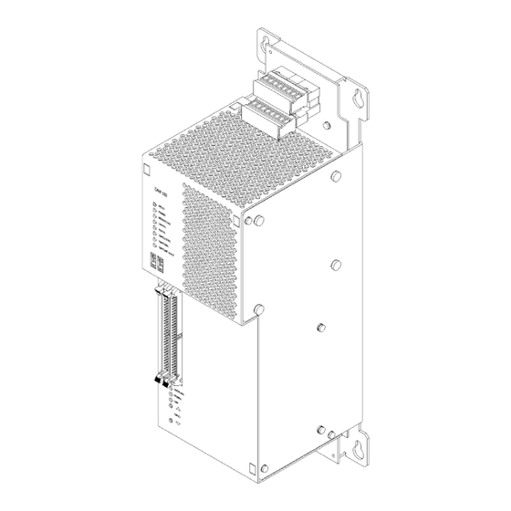
Figure 1
ZAM-180
s
Advertisement
Table of Contents

Summary of Contents for Siemens ZAM-180
- Page 1 500-035600 / S24235-B6-A2 (70V) / S24205-B6-A3 (100V) INTRODUCTION The ZAM-180 is a CAN data bus module that contains two speaker zones and one audio amplifier, capable of operating at 25(150W), 70(180W) or 100(165W) VRMS. The two speaker zones can be wired and operate as either...
-
Page 2: Operation
DAC-NET • SW update via PMI OPERATION The ZAM-180 receives its control and communication data from the DAC-NET and sends its status data to the DAC-NET via the CAN Bus. Therefore it takes 1 sub-address of the DAC-NET. Terminal Connections... - Page 3 OFF –external Check for failure on PSC, CC-5, wiring voltages fail MODULE FAIL yellow ON –general Failure on ZAM, ZAM-180 needs to be replaced trouble at ZAM CAN FAIL yellow ON –CAN interface Failure on AIC, DAC-NET, CC-5, back plane or...
-
Page 4: Pre-Installation
PRE-INSTALLATION The ZAM-180 takes one sub-address on the DAC-NET. To configure the CAN address use the two rotary-switches on the front panel (refer to Figure 2) Remove screws as shown in Figure 3 on the left and the right side of the ZAM-180 housing and remove the front plate. - Page 5 Setting the Speaker Line Voltage The speaker line voltage is set with connector terminals X4, X36 and X35. The amplifier supervision has to be configured for the appropriate line voltage, too. Amplifier supervision is configured with jumpers on header X28. Speaker Line Voltage 100V Plug in the coded connector on connector terminal X35 and set jumper X28 position 1-2.
-
Page 6: Installation
INSTALLATION Remove ELECTRICAL POWER prior to working on equipment. The ZAM-180 mounts on the Mounting Plate (CAB-MP). The Mounting Plate may be located either “IN” or “OUT” of the enclosure to perform this installation procedure. If the Mounting Plate is located “IN” the enclosure you will have to gain access to it by opening the enclosure Inner and Outer doors. - Page 7 Mounting Plate (Refer to Figure 10). When the ZAM-180 is mounted correctly on the Mounting Plate it will be flush on the top, bottom, and right with the Mounting Plate and the mounting screw holes of the PSC-12 will align with the threaded posts.
- Page 8 WIRING Remove ELECTRICAL POWER prior to working on equipment. All field wiring of the ZAM-180 is connected to the terminal blocks on the upper side of the ZAM-180. The screw terminals can accommodate one 12-24 AWG(Ø 0,5mm-2,5mm²) or two 16-24 AWG, (Ø 0,5mm-1,0mm²).
- Page 9 Class B, or 2 x Class B. Class A: The speaker line is looped back to the system. The end of line resistor (EOL) is connected directly at the ZAM-180 (CC-5/-2). In this configuration the line works during an open circuit condition by feeding it from both sides.
- Page 10 Class B: A configuration, where the end of line resistor is at the end of the speaker line. The ZAM-180 is capable of single Class B wiring if the unused speaker line is connected to an EOL Shield Loc. Audio IN B Loc.
- Page 11 Speaker Line 1 A EOL = 68k P/N 140-034728 (US/CA) C24235-A1-K13 (DE) Speaker Line 1 B shipped with the ZAM-180 In Canada, mount using Model EL-33. NOTES (Speaker Lines and Backup Amplifier) NOTES (Local Switch) Wiring can be Class A or Class B.
-
Page 12: Electrical Ratings
Installation Instruction A24205-A334-B844 (English) or A24205-A334-A844 (German) Order No. A24205-A334-B832 © Siemens Gebäudesicherheit GmbH & Co. oHG 2002 Siemens Building Technologies, Inc. Florham Park, New Jersey 07932 (Edition 1) Siemens Building Technologies, Ltd. Brampton, Ontario L6T 5E4 CN P/N 315-035600-2...


