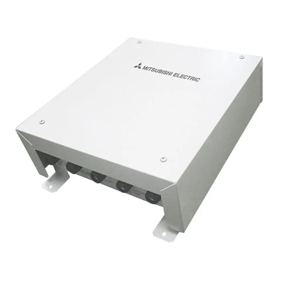
Mitsubishi Electric PAC-IF013B-E Manual
Hide thumbs
Also See for PAC-IF013B-E:
- Installation manual (24 pages) ,
- Installation manual (16 pages)
Table of Contents
Advertisement
Quick Links
INTERFACE
Modbus manual
[Model Name]
PAC-IF013B-E
PAC-SIF013B-E
Related document:
Refer to the following manual
• PAC-IF013B-E/PAC-SIF013B-E
INSTALLATION MANUAL
This manual describes the Modbus communication only. For
safety precautions, make sure to read installation manual of
PAC-IF013B-E/PAC-SIF013B-E.
CONTENTS
1. System ........................................................ 2
2. Communication specification .................. 3
3. Communication timing .............................. 3
4. Connecting Modbus input ........................ 4
6. Function code and Data address .................. 5
7. System Design Responsibility ................. 7
8. Laws and Regulations .............................. 7
September 2015
Advertisement
Table of Contents

Summary of Contents for Mitsubishi Electric PAC-IF013B-E
-
Page 1: Table Of Contents
INTERFACE Modbus manual September 2015 Related document: [Model Name] Refer to the following manual • PAC-IF013B-E/PAC-SIF013B-E PAC-IF013B-E INSTALLATION MANUAL PAC-SIF013B-E This manual describes the Modbus communication only. For safety precautions, make sure to read installation manual of PAC-IF013B-E/PAC-SIF013B-E. CONTENTS 1. System ............2 2. -
Page 2: System
System Using function Step Input Number of Intelligent multiple System *3 by Modbus mode type outdoor unit outdoor unit control Writing Manual Modbus AHU local Outdoor Interface controller unit Reading (Input and Remote monitoring) controller Apply *4 ■When not monitoring sub interfaces AHU local Interface Outdoor unit... -
Page 3: Communication Specification
Communication specification Item Description Interface RS-485 Communication method Half-duplex Connectable units Max.:31 Slave address can be set by DIP SW on the interface controller board. SW 4-1 SW 4-2 SW 4-3 SW 4-4 SW 4-5 Slave adress ••• ••• Baud rate Selectable from: 1200/2400/4800/9600/19200/38400/57600 Baud rate can be set by DIP SW on the interface controller board. -
Page 4: Connecting Modbus Input
Shield < Photo 4.1 > Note : •Termination resistor is NOT mounted in the circuit on PAC-IF013B-E/PAC-SIF013B-E. Therefore, if you install PAC-IF013B-E/PAC-SIF013B-E at line end, connect a termination resistor. 120Ω PAC-(S)IF013B-E < Fig. 4.1 > < Table 4.1 : Cable specifications >... -
Page 5: Led Display Detail For Modbus Connection
LED Display detail for Modbus connection LED display LED4 No communication : Not lighted During Communication : 1 blinking Communication error : Lighted Function code and Data address 6.1 Coils Read using function code 01 and write using function code 05/15. Function code 05 is single coil register, and function code 15 is multiple coil register. - Page 6 Function code and Data address < Continued from the previous page. > < Table 6 : Error codes > Error code Error code Error code Error code Discription Discription (Modbus) (Remote controller) (Modbus) (Remote controller) 5101 6832 "E3" or "E5" 6833 5102 1503...
-
Page 7: System Design Responsibility
A value contained in the query data field is not an allowable value for the slave (the interface unit). System Design Responsibility ● Mitsubishi Electric does not take any responsibility on the local system design of Modbus communication. Laws and Regulations... - Page 8 This product is designed and intended for use in the residential, commercial and light-industrial environment. HEAD OFFICE: TOKYO BLDG., 2-7-3, MARUNOUCHI, CHIYODA-KU, TOKYO 100-8310, JAPAN Authorised representative in EU: MITSUBISHI ELECTRIC EUROPE B.V. HARMAN HOUSE, 1 GEORGE STREET, UXBRIDGE, MIDDLESEX UB8 1QQ, U.K. RG79F084H01...
- Page 9 Related Links Model Number: PAC-SIF013B-E PAC-(S)IF013B-E Modbus Manual PAC-(S)IF013B-E Parts Catalogue PAC-IF013B-E AHU Design Guideline (RG79F087H03) PAC-IF013B-E Installation & Operation Manual (RG79F030H04)


