Sign In
Upload
Manuals
Brands
GE Manuals
Medical Equipment
BrightSpeed Elite
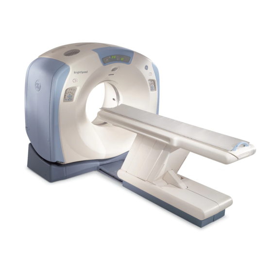
User Manuals: GE BrightSpeed Elite CT Scanner
Manuals and User Guides for GE BrightSpeed Elite CT Scanner. We have
1
GE BrightSpeed Elite CT Scanner manual available for free PDF download: Preinstallation Manual
GE BrightSpeed Elite Preinstallation Manual (170 pages)
Brand:
GE
| Category:
Medical Equipment
| Size: 9.2 MB
Table of Contents
Table of Contents
16
Chapter 1 Introduction
27
Section 1.0 Site Readiness
27
Customer Room Prep Items
28
Responsibility of Purchaser
28
Manufacturer's System Level Siting Requirements
29
Purchaser Site Preparation Work
29
Meeting Site Ready Requirements
30
Quick Installs
30
Two-Step" and Upgrade Installs
30
Site Ready Inspection Visit
31
Pre-Installation Checklist
32
Schedule Date Commitments
32
5141177-100, Revision
33
General Site Planning
33
References for Specific Site Requirements
33
Equipment Compatibility
34
Network Connections
34
Miscellaneous Tasks
34
Emission Declaration
37
Medical Electrical Equipment for EMC
37
General Scope
37
Electromagnetic Emission
37
Immunity Declaration
38
Electromagnetic Immunity
38
Immunity Declaration Con't
39
Separation Distances
40
Limitations Management
40
Use Limitation
40
External Components
40
Installation Requirements & Environment Control
41
Cable Shielding & Grounding
41
This Product Complies the Radiated Emission as Per CISPR11 Group 1 Class a Standard Limits
41
Subsystem & Accessories Power Supply Distribution
41
Stacked Components & Equipment
41
Low Frequency Magnetic Field
41
Static Magnetic Field Limits
41
Electrostatic Discharge Environment & Recommendations
41
Chapter 2
43
Pre-Installation Overview
43
Dust/Dirt Contamination
43
Chemical Contamination
43
Walls, Ceiling and Floor
43
Irection Evision Right Peed Lite Dge Xcel Re Nstallation
44
Section 4.0 Broad-Band
44
Phone Line (for Optional Modem)
44
Section 6.0 Review
44
Brightspeed System Options
47
Chapter 3 System Catalog
47
Section 1.0 Option Catalog Numbers
47
Application
49
Configuration
49
Section 2.0 Base Scanner System
49
List of Control Room Layouts
51
List of Scan Room Layouts
51
Chapter 4 Room Planning
51
Required Systems Clearances
51
Regulatory Clearances
52
Section 2.0 Regulatory Clearances
52
Console Subsystem
53
Regulated Minimum Working Clearance by Major Subsystem
53
Regulatory Code Description
53
Gantry Subsystem
54
NGPDU Subsystem
54
Terms and Definitions
57
Additional Regulatory Clearance Information
58
Egress Clearance
58
Minimum Room Size (Limited Access)
58
Operational Caution
58
Regulatory Caution
58
Minimum Room Size
59
Recommended Room Size
59
System Specifications (Brightspeed)
59
Typical Room Size
59
How to Measure
60
Minimum Room Size & Requirement Layouts
61
Recommended Room Size & Requirement Layouts
63
Section 3.0 Service Clearances
64
Gantry Service Clearance
65
Service Clearances for Single Service Engineer
65
Console Service Clearance
66
Introduction of Short Footprint Function
66
Power Distribution Unit (NGPDU) Service Clearance
66
Short Footprint Consideration
66
Instruction of Using Short Footprint Function
67
Control Room Considerations
69
Section 5.0 Recommended Layouts
69
Advantage Workstation (AW)
70
Storage Cabinet
70
Section 6.0 Component Dimensions
71
Power Distribution Unit
75
Power Distribution Unit (NGPDU)
75
Operator's Console
76
Freedom Workspace Table
79
Injector Control
83
Minimum Dimensions and Clearances
83
Options
83
System Operation
83
Structural Requirements
84
Figure
84
Floor Anchors
84
Floor Levelness
85
Floor Strength
85
Floor Vibration
85
Steady State Vibration
85
Transient Vibration
85
Ceiling Requirement
86
Equipment Location
86
Walls: Scan Window
86
Section 9.0 Network Connections
87
Customer Broad-Band Responsibilities
89
US Broad Band Process Overview
89
Section 10.0 Radiation Protection
91
Fluoro Stand Position
94
Scatter Plot of Fluoro - Body
94
Scatter Plot of Fluoro - Head
95
Section 11.0 Patient Environment
96
Chapter 5
97
Environmental Conditions
97
Temperature and Humidity Specifications
97
Temperature (Scan Room & Control Room)
97
Humidity (Scan Room & Control Room)
98
Other Guidelines
98
Section 2.0 Cooling Requirement
99
Altitude
99
Electro-Magnetic Interference (EMI)
100
Gantry and Table
100
Color Monitor
100
Console / Computer Equipment
100
Magnetic Media
100
Pdu
100
EMI Reduction
101
Ups
101
Sample Room Layout, Showing Approximate EMI Requirements
102
Equipment EMI "Envelopes
102
Section 5.0 System Component Noise Levels
102
Floor Loading and Weights
103
Chapter 6
103
Gantry
103
Figure
103
Floor Loading
103
Mounting Data, Including Seismic
105
Typical Floor Anchor, Gantry and Table
106
Gantry Anchor Location
107
Patient Table (H-Power)
108
Patient Table (GT1700)
109
GOC4/LCGOC/AIO Operator Console
112
TIO and NIO16 Console Seismic Mounting Hole Position
113
Chapter 7
115
Delivery and Storage Requirements
115
Delivery to the Facility
115
Loading Dock Deliveries (Preferred Methods)
115
Ground (Non-Loading Dock) Deliveries
115
Lift-Gate Truck
115
Tilt Bed Truck
115
Forklift Truck
116
Rigging
116
Delivery to the Scan Suite
117
Lifting
117
Stairway Deliveries
117
Floor Protection
117
Un-Loading and Un-Packing the System
117
Section 3.0 Dollies
118
Installations Within the United States
118
Zero Clearance Dollies
118
Tilting Table Dollies
118
Installation Outside of the United States
118
Gantry with Dollies
119
Gantry Considerations
119
Table
120
Figure
120
Section 5.0
120
HP-Power Table
120
GT1700 Table
120
Console Considerations
120
Console Packing
121
Section 7.0 PDU Considerations
121
Section 8.0 Storage Requirements
122
Short Term Storage (Less than 6 Months)
122
Construction-Site Storage
122
Long Term Storage (6 Months or More)
122
Package Symbols (Storage)
123
Extreme Temperature Transportation and Deliveries
123
Site Environmental Considerations
124
Dust/Dirt Contamination
124
Chemical Contamination
124
Section 11.0 Handling Requirements
124
Transportation
124
Handling Requirements
124
Proper Gantry Strap Location
125
Avoid Dropping
125
Avoid Shocks and Vibrations
125
Avoid Tipping
125
Inclines and Flat-Bed Truck Removal
125
Chapter 8
127
Power Requirements
127
Section 1.0 Introduction
127
Section 2.0 System Input Power
128
Power Source Configuration
128
Rating
128
Regulation
129
Phase Imbalance
129
Sags, Surges & Transients
129
Grounding
129
Recommended Power Distribution System
130
System Ground Map
132
Section 4.0 Ground System
132
Interconnection Data
133
Chapter 9
133
Section 1.0 Introduction
133
Component Designators
133
Interconnect Runs, Wiring and Cables
134
GEMS Supplied (Optional, Short Run)
134
GEMS Supplied (Freedom Workspace Table Extended Cables Kit)
137
System Interconnect Diagram (with GOC4/LCGOC Console and GOB Board)
139
System Interconnect Diagram (with All-In-One Console and IPC Board)
140
System Interconnect Diagram (with TIO Console and IPC Board)
141
System Interconnect Diagram (with NIO16 Console and IPC Board)
142
GEMS Supplied (Optional, Long Run)
143
GEMS Supplied (Cables of Options)
146
Contractor (Customer) Supplied
148
Interconnection Runs
149
Contractor Supplied Components
150
Section 5.0 Fuse
150
Typical UPS Interconnect
152
Section 6.0 UPS Interconnect
152
Primary Power Disconnect (A1)
153
Typical Customer Supplied Wiring
153
Primary Power Disconnect
153
Primary Power Disconnect (A1) - Fusible Disconnect and Magnetic Contactor
154
Scan Room Warning Light & Door Interlock
155
Recommended Power Distribution System (for Europe)
156
Appendix A Alternate Cover Removal Options
159
Overview
159
Front Cover Removal
159
Rear Cover Removal
160
Condition References
160
Advertisement
Advertisement
Related Products
GE BrightSpeed Edge
GE BrightSpeed Excel
GE CARESCAPE Monitor B850
GE CARESCAPE B125
GE CARESCAPE B105
GE BiliSoft
GE B20
GE B40
GE LOGIQ LP5 ADVANCED BT11
GE CARESCAPE B650
GE Categories
Refrigerator
Ranges
Microwave Oven
Air Conditioner
Dishwasher
More GE Manuals
Login
Sign In
OR
Sign in with Facebook
Sign in with Google
Upload manual
Upload from disk
Upload from URL