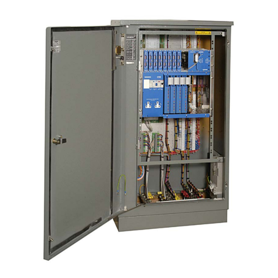
Siemens ST950/ Plus+ Installation Method Statement
Controller cabinet stool
Hide thumbs
Also See for ST950/ Plus+:
- User manual (178 pages) ,
- Handbook (154 pages) ,
- Handbook (107 pages)
Summary of Contents for Siemens ST950/ Plus+
- Page 1 ST950/ Plus+ Controller Cabinet Stool Installation Method Statement Issue 1 Sept-19...
-
Page 2: Table Of Contents
1 Introduction ......................3 Purpose ..................... 3 Contact Us ....................3 2 Installation of the Standard Siemens Mobility Controller Stool ......... 4 Installation of Standard Stool Frame ............4 Back-fill and In-fill the Stool ................ 5 Sealing the Base ..................6 3 Installation of a Plus Controller Stool .............. -
Page 3: Introduction
Installation Method Statement NTRODUCTION 1.1 Purpose The purpose of this handbook is to describe the approved Siemens installation procedures for the ST900/ ST950 stool product range manufactured by Siemens, this includes the standard stool and the Plus stool. Status of Development Ongoing development means that some of the delivered items may differ in detail from the photographs included in this handbook. -
Page 4: Installation Of The Standard Siemens Mobility Controller Stool
Controller Cabinet Stool Installation Method Statement NSTALLATION OF THE TANDARD IEMENS OBILITY ONTROLLER TOOL 2.1 Installation of Standard Stool Frame 1. Excavate a pit in the ground to suit the stool size. Refer to Figure 1. 2. Locate and prepare the ducting to enter the controller base in a suitable position. 3. -
Page 5: Back-Fill And In-Fill The Stool
Controller Cabinet Stool Installation Method Statement Apply silicone sealant Apply silicone sealant between stool and case between stool and case 996/4/22026/100 996/4/22026/100 Figure 1 - Stool Installation with flagstone 2.2 Back-fill and In-fill the Stool On completion of the cable installation and testing the controller cabinet and stool can be back-filled by using the appropriate material for the site layout. -
Page 6: Sealing The Base
Siemens base seal kit part number 667/1/20214/000 OR GB7:4/MC3584 SEALANT ISP PC5882-BLACK is recommended for sealing the base. Guidance for In-Filling The in-filling, kiln dried sand, must be brought to ground level or above and compacted. -
Page 7: Installation Of A Plus Controller Stool
Controller Cabinet Stool Installation Method Statement NSTALLATION OF A ONTROLLER TOOL 3.1 Installation of a Plus+ Cabinet Stool Frame 1. Refer to Figure 2 for the general method of installation and dimensions. 2. Excavate a pit in the ground approximately 100cm long x 70cm wide x 450cm deep. 3. - Page 8 Controller Cabinet Stool Installation Method Statement cannot be fixed with the studs facing downwards then the Temporary Plus+ Cabinet Stool Lid can be used (667/2/53028/000). Figure 2 – Plus+ Stool Installation Controller Cabinet Stool Installation Page 8 of 13 Issue 1 Method Statement 667/CC/53060/000 Unrestricted...
- Page 9 Controller Cabinet Stool Installation Method Statement Figure 3 – Example of ducting - This installation example uses flexible utility duct to redirect existing ducts Figure 4 – Shuttering in place Controller Cabinet Stool Installation Page 9 of 13 Issue 1 Method Statement 667/CC/53060/000 Unrestricted...
- Page 10 Controller Cabinet Stool Installation Method Statement Figure 5 – Showing ducting routes and back fill Figure 6 – Checking door opening for finished surface Controller Cabinet Stool Installation Page 10 of 13 Issue 1 Method Statement 667/CC/53060/000 Unrestricted...
-
Page 11: Installation Of A Plus+ Sealed Cabinet Base
Controller Cabinet Stool Installation Method Statement 3.2 Installation of a Plus+ Sealed Cabinet Base 1. Remove the sealed base plate from the stool 2. Run a bead of silicone, 996/4/22026/100, all around the top rim of the stool ensuring no gaps are left. -
Page 12: Bringing Street Cables Into The Cabinet (Earthing And Sealing Cables)
Controller Cabinet Stool Installation Method Statement 3.3 Bringing street cables into the cabinet (earthing and sealing cables). The components on the Sealed Base Kit are described in Figure 8. 1. Loosen nuts on the top clamps. 2. Remove top clamp. 3. - Page 13 Controller Cabinet Stool Installation Method Statement Grease on studs There should be some grease on each stud, please make sure it is there. If there is no grease then it is very likely that the nut could cease making in unremovable in the future. If there is no grease then please apply either carbon grease or copper grease to the stud.
- Page 14 Siemens Mobility Limited Subject to change without prior notice Sopers Lane Order No. 667/CC/53060/000 Poole © Siemens Mobility Limited, 2019 For more For more BH17 7ER information on Plus+ information on Plus+ scan the QR code scan the QR code United Kingdom www.siemens.co.uk/traffic...


