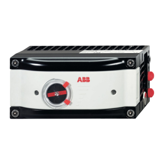
ABB TZIDC-210 Operating Instructions Manual
Electro-pneumatic positioner for profibus pa with flameproof enclosure
Hide thumbs
Also See for TZIDC-210:
- Operating instructions manual (68 pages) ,
- Operating instruction (68 pages) ,
- Commissioning instructions (34 pages)
Summary of Contents for ABB TZIDC-210
- Page 1 Operating Instructions Electro-Pneumatic Positioner TZIDC-210 42/18-81 EN for PROFIBUS PA with flameproof enclosure ® P R O F I PROCESS FIELD BUS B U S...
- Page 2 More information, e.g. regarding configuration, operation and ordering details, is available on CD. © Copyright 2006 by ABB Automation Products GmbH Modifications reserved This document is subject to copyright. It is intended to help the user operate the equipment safely and efficiently.
-
Page 3: Table Of Contents
General safety instructions ..................6 Device-specific safety instructions................. 7 1.2.1 General ......................7 1.2.2 Special instructions for TZIDC-210 positioners of explosion protection type Ex d (type Doc. 901132, type examination certificate DTM 02 ATEX E 029 X): ....................7 1.2.3 Pneumatic safety ..................8 1.2.4... - Page 4 Functional test / maintenance ................30 3.5.1 Functional test of the shutdown module ............31 4 Technical data ......................32 Basic model......................32 Options ........................36 5 Certificates ........................38 Appendix A: Configuration overview ................ 66 Electro-pneumatic positioner TZIDC-210 42/18-81 EN...
-
Page 5: Important Information
If the information in this document is insufficient in any situation, please contact our service de- partment, who will be happy to help you. Please read this document carefully before installation and commissioning. 42/18-81 EN Electro-pneumatic positioner TZIDC-210... -
Page 6: Safety Summary
• careful maintenance The regulations, standards and directives referred to in this manual are applicable in Germany. When using the TZIDC-210 positioner outside the German jurisdiction, the rel- evant regulations, standards and directives applicable in the country where the device is used must be observed. -
Page 7: Device-Specific Safety Instructions
Ex d (type Doc. 901132, type examination certificate DTM 02 ATEX E 029 X): • Do not open a TZIDC-210 positioner installed and run in a hazardous area directly upon switch-off. Always wait for at least five minutes. Otherwise, some components inside the housing may still be hot and cause an explosion. -
Page 8: Pneumatic Safety
When connecting a power source for test purposes without establishing a bus communication (e.g. when executing the Autoadjust function), a supply voltage between 9.0 V DC and a maximum of 32 V DC can be applied. Electro-pneumatic positioner TZIDC-210 42/18-81 EN... -
Page 9: Explosion Protection
All cable shields must be kept as short as possible and have to be connected to protective ground on both sides (use the grounding screw in the TZIDC-210 connection compartment on the device side). •... -
Page 10: Correct Use
18-0.33 EN. 2.2 CE compliance information We declare that we are the manufacturer of the TZIDC-210 positioner and that the prod- uct conforms with the EMC Directive 89/336/CEE as of May 1989 and meets the require- ments of the following standards: •... -
Page 11: Installing And Commissioning
60° for mounting to linear actuators and 120° for mount- ing to rotary actua- tors. The minimum angle is always 25°. Operating range for linear actuators Operating range for rotary actuators -30° -60° Fig. 3 Positioner ranges 42/18-81 EN Electro-pneumatic positioner TZIDC-210... -
Page 12: Operating Conditions At The Installation Site
3.1.2 Operating conditions at the installation site Before installing check to ensure that the specifications in terms of safety and control applicable to the TZIDC-210 positioner will not be exceeded at the installation site of the actuator or final control element. - Page 13 • Slip the plain washer (8) onto the screw (7), insert the screw into the lever and counter with the nut (9). Fig. 6 Assembling the lever 42/18-81 EN Electro-pneumatic positioner TZIDC-210...
- Page 14 3. Mount the lever and the angle bracket to the positioner Fig. 7 Mounting lever and angle bracket to TZIDC-210 • Attach the lever (1) to the positioner’s feedback shaft (2) (can only be mounted in one position due to the flat on the side of the feedback shaft).
- Page 15 Adjust the height of the positioner at the cast iron yoke or the columnar yoke until the lever is horizontal (at visual check) at half valve stroke. Check the unit for proper mounting after having made the pneumatic and IMPORTANT electrical connection (see chapter "Commissioning" on page 25). 42/18-81 EN Electro-pneumatic positioner TZIDC-210...
- Page 16 Minimum angle: 25° After mounting, check whether the positioner operates within the sensor range. Check the unit for proper mounting after having made the pneumatic and IMPORTANT electrical connection (see chapter "Commissioning" on page 25). Electro-pneumatic positioner TZIDC-210 42/18-81 EN...
-
Page 17: Mounting The Positioner To Rotary Actuators
(2.1), four spring washers (2.2), and four plain washers (2.3) for fastening the bracket to the actuator Fig. 11 Mounting kit for rotary actuators Tools required: Wrench 10 mm /13 mm Allen key 3 mm 42/18-81 EN Electro-pneumatic positioner TZIDC-210... - Page 18 Mounting the adapter screws is engaged on the side of the feedback shaft with the flat. 2. Attach the mounting bracket (1) to the positioner M6 screws Fig. 13 Attaching the mounting bracket to the positioner Electro-pneumatic positioner TZIDC-210 42/18-81 EN...
- Page 19 3. Attach the TZIDC-210 positioner to the actuator M5 screws Fig. 14 Attaching the positioner to the actuator After mounting, check whether the actuator’s operating range is in accordance with the positioner’s sensor range. IMPORTANT Check the unit for proper mounting after having made the pneumatic and electrical connection (see chapter "Commissioning"...
-
Page 20: Pneumatic Connection
We recommend pipes with the dimension 6 x 1 mm for the pneumatic piping. The amount of supply pressure has to be matched to the working pressure necessary for the actuation. The positioner's operating range is between 1.4 and 6 bar. Electro-pneumatic positioner TZIDC-210 42/18-81 EN...


